


IRF1010E is an n-channel enhancement MOSFET designed for high speed switching applications. It also has low turn ON resistance. Like any other MOSFET the IRF1010E is voltage controlled device and MOSFET state is decided by GATE voltage.
IRF1010E Pin Configuration
It has three pins namely GATE, DRAIN and SOURCE. The pin configuration of IRF1010E is given below.
Pin Number | Pin Name | Description |
3 | SOURCE | Normally connected to GROUND |
2 | DRAIN | Normally connected to LOAD |
1 | GATE | Normally used as TRIGGER to turn ON the MOSFET. |
IRF1010E Features and Specifications
- Advanced process technology
- Fully avalanche rated
- Fast switching
- Fifth generation HEXFET
- Maximum voltage across DRAIN and SOURCE: 60V
- Maximum continuous current allowed trough DRAIN: 81A
- Maximum pulsed DRAIN current: 330A
- Maximum voltage across GATE and SOURCE:20 V
- Maximum operating Temperature: 175ºC
- Maximum power dissipation: 170Watt
IRF1010E Equivalents
IRF1407, IRFB4110, IRFB4110G, IRFB4115, IRFB4310Z, IRFB4310ZG, IRFB4410
Where to Use IRF1010E?
There are many reasons for using IRF1010E, here are a few:
- When you want a high speed SWITCHING device for MEDIUM POWER LOADS. As mentioned above IRF1010E is specially designed for high speed switching of medium power loads so it is fairly popular in those areas.
- When you want low drop switching device. The MOSFET has very low turn ON resistance leading to very low drop during ON condition, which is a must condition in some applications.
- With low drop the MOSFET power loss will be less. With less power loss the efficiency of the system will be more. So the MOSFET is preferred for high efficiency applications.
How to use IRF1010E
IRF1010E MOSFET can be used like any other power MOSFETs, so let us consider an example circuit for IRF1010E as shown below.
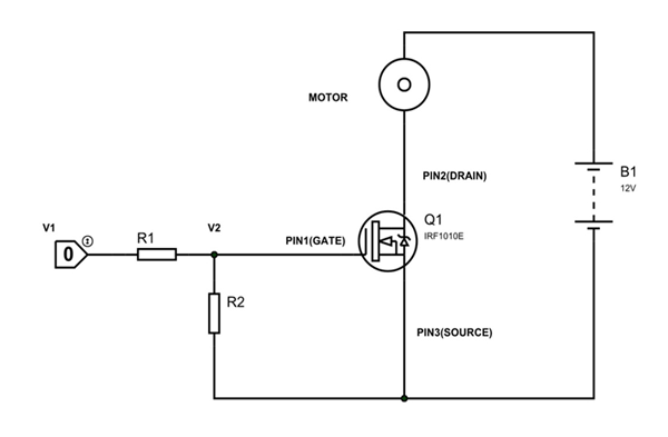
In the above circuit we are using IRF1010E as a simple switching device. In the circuit we are using a small motor as the LOAD. The TRIGGER for turning ON the MOSFET is provided by CONTROL UNIT (NOT MICROCONTROLLER as MICROCONTROLLER cannot provide voltages higher than +5V).The SOURCE is grounded. The power source here is +12V battery.
CONTROL UNIT trigger voltage = V1
GATE voltage = V2
The resistors R1 and R2 here form a voltage divider circuit to provide appropriate voltage at GATE. So they are chosen based on CONTROL UNIT trigger voltage (V1) and MOSFET GATE threshold voltage.
For example consider the CONTROL UNIT provides pulses of voltage +12V. Also for turning ON the MOSFET IRF1010E completely we need GATE voltage of 10V.
So V1 =+12V and V2 = +10V
We can choose R1 and R2 as,
R1 | R2 |
200Ω | 1KΩ |
400Ω | 2KΩ |
2KΩ | 10KΩ |
With the voltage divider circuit formed by any set of above table will give exact +10V at MOSFET GATE. This Resistor set could be chosen without considering the current draw from MOSFET as it is negligible. These resistances could be chosen approximately for normal applications.
In the circuit above under normal conditions the MOSFET will be OFF as these will be no GATE voltage. And when MOSFET is OFF the complete VCC appears across it. In this case the DRAIN current will be zero. Since DRAIN current is zero the MOTOR will sit idle.
When the CONTROL UNIT provides voltage pulses there will be GATE voltage. With GATE voltage being present the MOSFET gets tuned ON. With that there will be DRAIN current which flows through MOTOR. Having current flow the MOTOR stars rotating. The MOTOR will be keep rotating until there will be GATE voltage.
When the CONTROL UNIT output goes LOW the GATE voltage also becomes LOW. The MOSFET gets turned OFF when the GATE voltage drops below the threshold voltage. Under OFF state the DRAIN current also becomes ZERO, bringing MOTOR to STOP.
By above scenario you can tell the MOSFET is used as switching device with trigger being provided by control unit. This way we can use IRF1010E as a switching device in any application. The circuit used above is a simple testing circuit and is not an application circuit. The application circuit must have required arrangements like HEAT SINK, FLYBACK DIODE etc.
Applications
- Basically any switching applications
- speed control units
- Lighting systems
- PWM applications
- Relay drivers
- Switch mode power supply
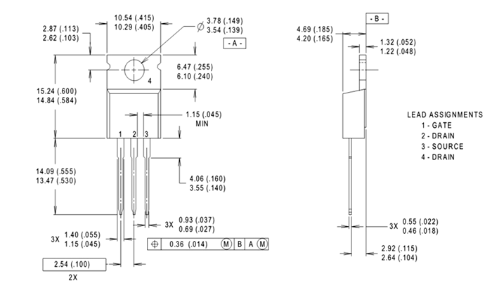
2D-Model
All measurements are in millimeters (inches)
")


")


")


")


")


")


")


