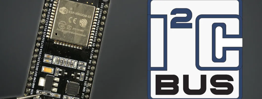
The ESP32 has two I2C bus interfaces that can serve as I2C master or slave. In this tutorial we’ll take a look at the I2C communication protocol with the ESP32 using Arduino IDE: how to choose I2C pins, connect multiple I2C devices to the same bus and how to use the two I2C bus interfaces.
In this tutorial, we’ll cover the following concepts:
- Connecting I2C Devices with ESP32
- Scan I2C Address with ESP32
- Use Different I2C Pins with ESP32 (change default I2C pins)
- ESP32 with Multiple I2C Devices
- ESP32 Using Two I2C Bus Interfaces
- ESP32 I2C Master and Slave (I2C Communication Between Two ESP32)
We’ll program the ESP32 using Arduino IDE, so before proceeding with this tutorial you should have the ESP32 add-on installed in your Arduino IDE. Follow the next tutorial to install the ESP32 on the Arduino IDE, if you haven’t already.
Introducing ESP32 I2C Communication Protocol
I²C means Inter Integrated Circuit (it’s pronounced I-squared-C), and it is a synchronous, multi-master, multi-slave communication protocol. You can connect :
- multiple slaves to one master: for example, your ESP32 reads from a BME280 sensor using I2C and writes the sensor readings in an I2C OLED display.
- multiple masters controlling the same slave: for example, two ESP32 boards writing data to the same I2C OLED display.
We use this protocol many times with the ESP32 to communicate with external devices like sensors and displays. In these cases, the ESP32 is the master chip and the external devices are the slaves.
We have several tutorials with the ESP32 interfacing with I2C devices:
- 0.96 inch I2C OLED display with ESP32
- ESP32 Built-in OLED Board
- I2C LCD Display with ESP32
- BMP180 with ESP32
- BME280 with ESP32
ESP32 I2C Bus Interfaces
The ESP32 supports I2C communication through its two I2C bus interfaces that can serve as I2C master or slave, depending on the user’s configuration. Accordingly to the ESP32 datasheet, the I2C interfaces of the ESP32 supports:
- Standard mode (100 Kbit/s)
- Fast mode (400 Kbit/s)
- Up to 5 MHz, yet constrained by SDA pull-up strength
- 7-bit/10-bit addressing mode
- Dual addressing mode. Users can program command registers to control I²C interfaces, so that they have more flexibility
Connecting I2C Devices with ESP32
I2C communication protocol uses two wires to share information. One is used for the clock signal (SCL) and the other is used to send and receive data (SDA).
Note: in many breakout boards, the SDA line may also be labeled as SDI and the SCL line as SCK.

The SDA and SCL lines are active low, so they should be pulled up with resistors. Typical values are 4.7k Ohm for 5V devices and 2.4k Ohm for 3.3V devices.
Most sensors we use in our projects are breakout boards that already have the resistors built-in. So, usually, when you’re dealing with this type of electronics components you don’t need to worry about this.
Connecting an I2C device to an ESP32 is normally as simple as connecting GND to GND, SDA to SDA, SCL to SCL and a positive power supply to a peripheral, usually 3.3V (but it depends on the module you’re using).
| I2C Device | ESP32 |
| SDA | SDA (default is GPIO 21) |
| SCL | SCL (default is GPIO 22) |
| GND | GND |
| VCC | usually 3.3V or 5V |
When using the ESP32 with Arduino IDE, the default I2C pins are GPIO 22 (SCL) and GPIO 21 (SDA) but you can configure your code to use any other pins.
Recommended reading: ESP32 GPIO Reference Guide
Scan I2C Address with ESP32
With I2C communication, each slave on the bus has its own address, a hexadecimal number that allows the ESP32 to communicate with each device.
The I2C address can be usually found on the component’s datasheet. However, if it is difficult to find out, you may need to run an I2C scanner sketch to find out the I2C address.
You can use the following sketch to find your devices’ I2C address.
/*********
  Rui Santos
  Complete project details at https://randomnerdtutorials.com
*********/

#include <Wire.h>

void setup() {
  Wire.begin();
  Serial.begin(115200);
  Serial.println("\nI2C Scanner");
}

void loop() {
  byte error, address;
  int nDevices;
  Serial.println("Scanning...");
  nDevices = 0;
  for(address = 1; address < 127; address++ ) {
    Wire.beginTransmission(address);
    error = Wire.endTransmission();
    if (error == 0) {
      Serial.print("I2C device found at address 0x");
      if (address<16) {
        Serial.print("0");
      }
      Serial.println(address,HEX);
      nDevices++;
    }
    else if (error==4) {
      Serial.print("Unknow error at address 0x");
      if (address<16) {
        Serial.print("0");
      }
      Serial.println(address,HEX);
    }
  }
  if (nDevices == 0) {
    Serial.println("No I2C devices found\n");
  }
  else {
    Serial.println("done\n");
  }
  delay(5000);
}
You’ll get something similar in your Serial Monitor. This specific example is for an I2C LCD Display.

Use Different I2C Pins with ESP32 (change default I2C pins)
With the ESP32 you can set almost any pin to have I2C capabilities, you just need to set that in your code.
When using the ESP32 with the Arduino IDE, use the Wire.h library to communicate with devices using I2C. With this library, you initialize the I2C as follows:
Wire.begin(I2C_SDA, I2C_SCL);So, you just need to set your desired SDA and SCL GPIOs on the I2C_SDA and I2C_SCL variables.
However, if you’re using libraries to communicate with those sensors, this might not work and it might be a bit tricky to select other pins. That happens because those libraries might overwrite your pins if you don’t pass your own Wire instance when initializing the library.
In those cases, you need to take a closer look at the .cpp library files and see how to pass your own TwoWire parameters.
For example, if you take a closer look at the Adafruit BME280 library, you’ll find out that you can pass your own TwoWire to the begin() method.

So, the example sketch to read from the BME280 using other pins, for example GPIO 33 as SDA and and GPIO 32 as SCL is as follows.
/*
  Rui Santos
  Complete project details at https://RandomNerdTutorials.com/esp32-i2c-communication-arduino-ide/

  Permission is hereby granted, free of charge, to any person obtaining a copy
  of this software and associated documentation files.

  The above copyright notice and this permission notice shall be included in all
  copies or substantial portions of the Software.
*/

#include <Wire.h>
#include <Adafruit_Sensor.h>
#include <Adafruit_BME280.h>

#define I2C_SDA 33
#define I2C_SCL 32

#define SEALEVELPRESSURE_HPA (1013.25)

TwoWire I2CBME = TwoWire(0);
Adafruit_BME280 bme;

unsigned long delayTime;

void setup() {
  Serial.begin(115200);
  Serial.println(F("BME280 test"));
  I2CBME.begin(I2C_SDA, I2C_SCL, 100000);

  bool status;

  // default settings
  // (you can also pass in a Wire library object like &Wire2)
  status = bme.begin(0x76, &I2CBME);
  if (!status) {
    Serial.println("Could not find a valid BME280 sensor, check wiring!");
    while (1);
  }

  Serial.println("-- Default Test --");
  delayTime = 1000;

  Serial.println();
}

void loop() {
  printValues();
  delay(delayTime);
}

void printValues() {
  Serial.print("Temperature = ");
  Serial.print(bme.readTemperature());
  Serial.println(" *C");

  // Convert temperature to Fahrenheit
  /*Serial.print("Temperature = ");
  Serial.print(1.8 * bme.readTemperature() + 32);
  Serial.println(" *F");*/

  Serial.print("Pressure = ");
  Serial.print(bme.readPressure() / 100.0F);
  Serial.println(" hPa");

  Serial.print("Approx. Altitude = ");
  Serial.print(bme.readAltitude(SEALEVELPRESSURE_HPA));
  Serial.println(" m");

  Serial.print("Humidity = ");
  Serial.print(bme.readHumidity());
  Serial.println(" %");

  Serial.println();
}
Let’s take a look at the relevant parts to use other I2C pins.
First, define your new I2C pins on the I2C_SDA and I2C_SCL variables. In this case, we’re using GPIO 33 and GPIO 32.
#define I2C_SDA 33
#define I2C_SCL 32
Create a new TwoWire instance. In this case, it’s called I2CBME. This simply creates an I2C bus.
TwoWire I2CBME = TwoWire(0);In the setup(), initialize the I2C communication with the pins you’ve defined earlier. The third parameter is the clock frequency.
I2CBME.begin(I2C_SDA, I2C_SCL, 400000);Finally, initialize a BME280 object with your sensor address and your TwoWire object.
status = bme.begin(0x76, &I2CBME);After this, you can use use the usual methods on your bme object to request temperature, humidity and pressure.
Note: if the library you’re using uses a statement like wire.begin() in its file, you may need to comment that line, so that you can use your own pins.
ESP32 with Multiple I2C Devices
As we’ve mentioned previously, each I2C device has its own address, so it is possible to have multiple I2C devices on the same bus.
Multiple I2C devices (same bus, different addresses)
When we have multiple devices with different addresses, it is trivial how to set them up:
- connect both peripherals to the ESP32 SCL and SDA lines;
- in the code, refer to each peripheral by its address;
Take a look at the following example that gets sensor readings from a BME280 sensor (via I2C) and displays the results on an I2C OLED display.
/*
  Rui Santos
  Complete project details at https://RandomNerdTutorials.com/esp32-i2c-communication-arduino-ide/

  Permission is hereby granted, free of charge, to any person obtaining a copy
  of this software and associated documentation files.

  The above copyright notice and this permission notice shall be included in all
  copies or substantial portions of the Software.
*/

#include <Wire.h>
#include <Adafruit_GFX.h>
#include <Adafruit_SSD1306.h>
#include <Adafruit_Sensor.h>
#include <Adafruit_BME280.h>

#define SCREEN_WIDTH 128 // OLED display width, in pixels
#define SCREEN_HEIGHT 64 // OLED display height, in pixels

Adafruit_SSD1306 display(SCREEN_WIDTH, SCREEN_HEIGHT, &Wire, -1);

Adafruit_BME280 bme;

void setup() {
  Serial.begin(115200);

  if(!display.begin(SSD1306_SWITCHCAPVCC, 0x3C)) {
    Serial.println(F("SSD1306 allocation failed"));
    for(;;);
  }

  bool status = bme.begin(0x76);
  if (!status) {
    Serial.println("Could not find a valid BME280 sensor, check wiring!");
    while (1);
  }

  delay(2000);
  display.clearDisplay();
  display.setTextColor(WHITE);
}

void loop() {
  display.clearDisplay();
  // display temperature
  display.setTextSize(1);
  display.setCursor(0,0);
  display.print("Temperature: ");
  display.setTextSize(2);
  display.setCursor(0,10);
  display.print(String(bme.readTemperature()));
  display.print(" ");
  display.setTextSize(1);
  display.cp437(true);
  display.write(167);
  display.setTextSize(2);
  display.print("C");

  // display humidity
  display.setTextSize(1);
  display.setCursor(0, 35);
  display.print("Humidity: ");
  display.setTextSize(2);
  display.setCursor(0, 45);
  display.print(String(bme.readHumidity()));
  display.print(" %");

  display.display();

  delay(1000);
}
Because the OLED and the BME280 have different addresses, we can use the same SDA and SCL lines without any problem. The OLED display address is 0x3C and the BME280 address is 0x76.
if(!display.begin(SSD1306_SWITCHCAPVCC, 0x3C)) {
  Serial.println(F("SSD1306 allocation failed"));
  for(;;);
}

bool status = bme.begin(0x76);
if (!status) {
  Serial.println("Could not find a valid BME280 sensor, check wiring!");
  while (1);
}
Recommended reading: ESP32 OLED Display with Arduino IDE
Multiple I2C devices (same address)
But, what if you have multiple peripherals with the same address? For example, multiple OLED displays or multiple BME280 sensors? There are several solutions.
- change the device I2C address;
- use an I2C multiplexer.
Changing the I2C address
Many breakout boards have the option to change the I2C address depending on its circuitry. For example, that a look at the following OLED display.

By placing the resistor on one side or the other, you can select different I2C addresses. This also happens with other components.
Using an I2C Multiplexer
However, in this previous example, this only allows you to have two I2C displays on the same bus: one with 0x3C address and another with 0x3D address.
Additionally, sometimes it is not trivial changing the I2C address. So, in order to have multiple devices with the same address in the same I2C bus, you can use an I2C multiplexer like the TCA9548A that allows you to communicate with up to 8 devices with the same address.

We have a detailed tutorial explaining how to use an I2C multiplexer to connect multiple devices with the same address to the ESP32: Guide for TCA9548A I2C Multiplexer: ESP32, ESP8266, Arduino.
ESP32 Using Two I2C Bus Interfaces
To use the two I2C bus interfaces of the ESP32, you need to create two TwoWire instances.
TwoWire I2Cone = TwoWire(0);
TwoWire I2Ctwo = TwoWire(1)
Then, initialize I2C communication on your desired pins with a defined frequency.
void setup() {
  I2Cone.begin(SDA_1, SCL_1, freq1);
  I2Ctwo.begin(SDA_2, SCL_2, freq2);
}
Then, you can use the methods from the Wire.h library to interact with the I2C bus interfaces.
A simpler alternative is using the predefined Wire() and Wire1() objects. Wire().begin() creates an I2C communication on the first I2C bus using the default pins and default frequency. For the Wire1.begin() you should pass your desired SDA and SCL pins as well as the frequency.
setup(){
  Wire.begin(); //uses default SDA and SCL and 100000HZ freq
  Wire1.begin(SDA_2, SCL_2, freq);
}
This method allows you to use two I2C buses, one of them uses the default parameters.
To better understand how this works, we’ll take a look at a simple example that reads temperature, humidity and pressure from two BME280 sensors.

Each sensor is connected to a different I2C bus.
- I2C Bus 1: uses GPIO 27 (SDA) and GPIO 26 (SCL);
- I2C Bus 2: uses GPIO 33 (SDA) and GPIO 32 (SCL);
/*
  Rui Santos
  Complete project details at https://RandomNerdTutorials.com/esp32-i2c-communication-arduino-ide/

  Permission is hereby granted, free of charge, to any person obtaining a copy
  of this software and associated documentation files.

  The above copyright notice and this permission notice shall be included in all
  copies or substantial portions of the Software.
*/

#include <Wire.h>
#include <Adafruit_Sensor.h>
#include <Adafruit_BME280.h>

#define SDA_1 27
#define SCL_1 26

#define SDA_2 33
#define SCL_2 32

TwoWire I2Cone = TwoWire(0);
TwoWire I2Ctwo = TwoWire(1);

Adafruit_BME280 bme1;
Adafruit_BME280 bme2;

void setup() {
  Serial.begin(115200);
  Serial.println(F("BME280 test"));

  I2Cone.begin(SDA_1, SCL_1, 100000);
  I2Ctwo.begin(SDA_2, SCL_2, 100000);

  bool status1 = bme1.begin(0x76, &I2Cone);
  if (!status1) {
    Serial.println("Could not find a valid BME280_1 sensor, check wiring!");
    while (1);
  }

  bool status2 = bme2.begin(0x76, &I2Ctwo);
  if (!status2) {
    Serial.println("Could not find a valid BME280_2 sensor, check wiring!");
    while (1);
  }

  Serial.println();
}

void loop() {
  // Read from bme1
  Serial.print("Temperature from BME1= ");
  Serial.print(bme1.readTemperature());
  Serial.println(" *C");

  Serial.print("Humidity from BME1 = ");
  Serial.print(bme1.readHumidity());
  Serial.println(" %");

  Serial.print("Pressure from BME1 = ");
  Serial.print(bme1.readPressure() / 100.0F);
  Serial.println(" hPa");

  Serial.println("--------------------");

  // Read from bme2
  Serial.print("Temperature from BME2 = ");
  Serial.print(bme2.readTemperature());
  Serial.println(" *C");

  Serial.print("Humidity from BME2 = ");
  Serial.print(bme2.readHumidity());
  Serial.println(" %");

  Serial.print("Pressure from BME2 = ");
  Serial.print(bme2.readPressure() / 100.0F);
  Serial.println(" hPa");

  Serial.println("--------------------");

  delay(5000);
}
Let’s take a look at the relevant parts to use the two I2C bus interfaces.
Define the SDA and SCL pins you want to use:
#define SDA_1 27
#define SCL_1 26

#define SDA_2 33
#define SCL_2 32
Create two TwoWire objects (two I2C bus interfaces):
TwoWire I2Cone = TwoWire(0);
TwoWire I2Ctwo = TwoWire(1);
Create two instances of the Adafruit_BME280 library to interact with your sensors: bme1 and bme2.
Adafruit_BME280 bme1;
Adafruit_BME280 bme2;
Initialize an I2C communication on the defined pins and frequency:
I2Cone.begin(SDA_1, SCL_1, 100000);
I2Ctwo.begin(SDA_2, SCL_2, 100000);
Then, you should initialize the bme1 and bme2 objects with the right address and I2C bus. bme1 uses I2Cone:
bool status = bme1.begin(0x76, &I2Cone); And bme2 uses I2Ctwo:
bool status1 = bme2.begin(0x76, &I2Ctwo);Now, you can use the methods from the Adafruit_BME280 library on your bme1 and bme2 objects to read temperature, humidity and pressure.
Another alternative
For simplicity, you can use the predefined Wire() and Wire1() objects:
- Wire(): creates an I2C bus on the default pins GPIO 21 (SDA) and GPIO 22 (SCL)
- Wire1(SDA_2, SCL_2, freq): creates an I2C bus on the defined SDA_2 and SCL_2 pins with the desired frequency.
Here’s the same example but using this method. Now, one of your sensors uses the default pins, and the other uses GPIO 32 and GPIO 33.
/*
  Rui Santos
  Complete project details at https://RandomNerdTutorials.com/esp32-i2c-communication-arduino-ide/

  Permission is hereby granted, free of charge, to any person obtaining a copy
  of this software and associated documentation files.

  The above copyright notice and this permission notice shall be included in all
  copies or substantial portions of the Software.
*/

#include <Wire.h>
#include <Adafruit_Sensor.h>
#include <Adafruit_BME280.h>

#define SDA_2 33
#define SCL_2 32

Adafruit_BME280 bme1;
Adafruit_BME280 bme2;

void setup() {
  Serial.begin(115200);
  Serial.println(F("BME280 test"));

  Wire.begin();
  Wire1.begin(SDA_2, SCL_2);

  bool status1 = bme1.begin(0x76);
  if (!status1) {
    Serial.println("Could not find a valid BME280_1 sensor, check wiring!");
    while (1);
  }

  bool status2 = bme2.begin(0x76, &Wire1);
  if (!status2) {
    Serial.println("Could not find a valid BME280_2 sensor, check wiring!");
    while (1);
  }

  Serial.println();
}

void loop() {
  // Read from bme1
  Serial.print("Temperature from BME1= ");
  Serial.print(bme1.readTemperature());
  Serial.println(" *C");

  Serial.print("Humidity from BME1 = ");
  Serial.print(bme1.readHumidity());
  Serial.println(" %");

  Serial.print("Pressure from BME1 = ");
  Serial.print(bme1.readPressure() / 100.0F);
  Serial.println(" hPa");

  Serial.println("--------------------");

  // Read from bme2
  Serial.print("Temperature from BME2 = ");
  Serial.print(bme2.readTemperature());
  Serial.println(" *C");

  Serial.print("Humidity from BME2 = ");
  Serial.print(bme2.readHumidity());
  Serial.println(" %");

  Serial.print("Pressure from BME2 = ");
  Serial.print(bme2.readPressure() / 100.0F);
  Serial.println(" hPa");

  Serial.println("--------------------");
  delay(5000);
}
You should get both sensor readings on your Serial Monitor.

ESP32 I2C Master and Slave (I2C Communication Between Two ESP32)
You can exchange data between two ESP32 boards using I2C communication protocol. One board needs to be set as a slave and another one as the master device.
The slave board contains the data that the master device can request.
You should wire both ESP32 boards using their respective I2C pins. Don’t forget to connect the GND pins together.

The previous picture shows the wiring for two ESP32 DOIT V1 boards. The default I2C pins are GPIO 21 (SDA) and GPIO 22 (SCL). If you’re using an ESP32-C3, ESP32-S3, or other model, the default I2C pins might be different. Please check the pinout for the board you’re using. You may also use custom I2C pins.
For a complete guide on how to exchange data between two ESP32 boards using I2C communication protocol, check the link below:
Wrapping Up
In this tutorial you learned more about I2C communication protocol with the ESP32. We hope you’ve found the information in this article useful.
To learn more about the ESP32 GPIOs, read our reference guide: ESP32 Pinout Reference: Which GPIO pins should you use?
Thanks for reading.













Comment