Overview
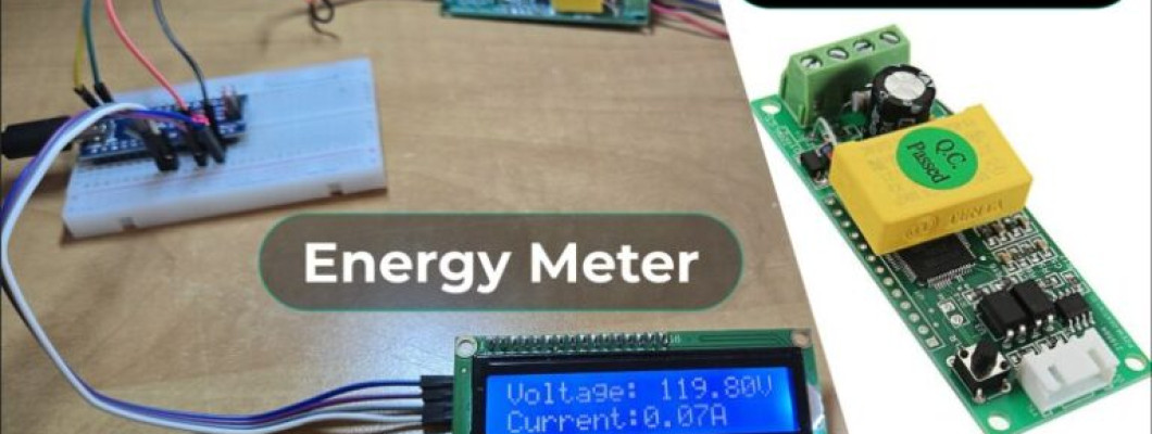
In this project, we will interface PZEM-004T (a compact AC power monitoring module) with Arduino to build a single phase AC Energy Meter. PZEM-004T Current and Voltage reader is a module that can measure current, voltage, active power (W), energy (kWh), frequency, and power factor. The module uses Modbus-RTU, a standard protocol for industrial communication. Microcontrollers such as Arduino can read PZEM-004T data via serial interfaces.
Earlier, we build the following energy meter projects:
- GSM-Based Prepaid Energy Meter
- IoT AC Energy Meter with ESP32 & Blynk
- Energy Meter using ESP32 & HMI Display
While the projects mentioned above are excellent for learning energy monitoring concepts and well-suited for hobbyist applications, their accuracy is limited due to the use of basic components like the ZMPT101B voltage sensor and SCT-013 current sensor. These modules are not precision instruments, and their measurements may exhibit noticeable deviations.
Hence we need a precise Energy Meter that can measure all parameters correctly. The PZEM-004T is used for the same applications. In this energy meter project, we will establish a serial communication between PZEM-004T & Arduino, and read the data such as Voltage, Current, Power, Energy, Power Factor & Frequency. All these data can be displayed on 16×2 LCD Display. Further you can make the IoT version of this project using the PZEM-004T and ESP32 microcontroller.
Bill of Materials
We need the following components to build this energy meter project. You can purchase all the components from the given links.
| S.N. | Components Name | Quantity | Purchase Link |
|---|---|---|---|
| 1 | Arduino Nano Board | 1 | Nerokas Store |
| 2 | PZEM-004T AC Meter Module | 1 | Nerokas Store |
| 3 | 16x2 LCD Display | 1 | Nerokas Store |
| 4 | Assorted Jumper Wires | 10 | Nerokas Store |
| 5 | Breadboard | 1 | Nerokas Store |

PZEM-004T Multifunction AC Digital Meter
The PZEM-004T is a compact, single-phase AC power monitoring module designed to measure electrical parameters such as voltage (80–260V), current (up to 100A via external CT), active power, energy consumption (kWh), frequency, and power factor.

It communicates via Modbus-RTU protocol over TTL serial (), making it easy to interface with microcontrollers like Arduino or ESP32. With built-in galvanic isolation and a non-invasive current transformer, it prioritizes safety. It is widely used in IoT applications, smart metering, and home automation projects.
PZEM-004T V3.0 Feature
- Voltage: 80–260V, 0.1V resolution, 0.5% accuracy
- Current: 0–10A (10A model), 0–100A (100A model), 0.001A resolution, 0.5% accuracy
- Active Power: 0–2.3kW (10A model), 0–23kW (100A model), 0.1W resolution, 0.5% accuracy
- Power Factor: 0.00–1.00, 0.01 resolution, 1% accuracy
- Frequency: 45–65Hz, 0.1Hz resolution, 0.5% accuracy
- Active Energy: 0–9999.99kWh, 1Wh resolution, 0.5% accuracy, resettable via software
- Over Power Alarm: Settable threshold, triggers alarm on exceedance
- Communication: RS485 (UART to RS485), 9600 baud, 8N1
Open CT & Close CT
Both Close CT and Open CT are 100A current transformers (Class 1.5 accuracy) compatible with the PZEM-004T module.

The Closed Current Transformer (CT) version of the PZEM-004T comes with a built-in, non-detachable CT, ensuring accurate and stable measurements. It is ideal for fixed installations where the sensor remains permanently connected to the measured circuit.
The Open Current Transformer (CT) version features a detachable clamp-type CT, allowing easy installation without disconnecting wires. This is useful for retrofitting or temporary monitoring applications where quick and flexible deployment is required.
Pinout of PZEM-004T V3.0
The PZEM-004T is an energy monitoring module that communicates via UART (RS485) and has the following pin configuration:
1. Power & Measurement Pins:
- L (Live) & N (Neutral): Connect to AC mains for voltage measurement and module power.
- CT+ & CT-: Connect to the current transformer (CT) for current measurement.
2. Communication Pins (TTL Serial or RS485):
- 5V: Power supply for the module (external 5V required).
- GND: Ground reference for communication.
- TX (Transmit): Sends data to the microcontroller.
- RX (Receive): Receives data from the microcontroller.
Module TTL Interface Note: This module’s TTL interface is passive and requires an external 5V power supply. All four pins (5V, RX, TX, GND) must be connected for proper communication. Operating temperature range: -20°C to +60°C.
Communication Protocol of PZEM-004T V3.0
1. Physical Layer Protocol
- Uses UART to RS485 communication interface
- Baud rate: 9600, 8 data bits, 1 stop bit, no parity
2. Application Layer Protocol
- Uses Modbus-RTU protocol
- Supported function codes:
- 0x03 (Read Holding Register)
- 0x04 (Read Input Register)
- 0x06 (Write Single Register)
- 0x41 (Calibration – internal use only, requires password 0x3721)
- 0x42 (Reset Energy)
3. Addressing
- Slave address range: 0x01 – 0xF7
- 0x00: Broadcast address (slave does not reply)
- 0xF8: General address (for single-slave environments and calibration)
4. Reading Measurement Results
- Master command format (8 bytes):
Slave Address + 0x04 + Register Address (High + Low) + No. of Registers (High + Low) + CRC (High + Low) - Correct Reply:
Slave Address + 0x04 + No. of Bytes + Register Data + CRC - Error Reply:
Slave Address + 0x84 + Error Code + CRC- 0x01: Illegal function
- 0x02: Illegal address
- 0x03: Illegal data
- 0x04: Slave error
5. Register Mapping
| Register Address | Description | Resolution |
|---|---|---|
| 0x0000 | Voltage | 0.1V |
| 0x0001-0x0002 | Current (Low & High) | 0.001A |
| 0x0003-0x0004 | Power (Low & High) | 0.1W |
| 0x0005-0x0006 | Energy (Low & High) | 1Wh |
| 0x0007 | Frequency | 0.1Hz |
| 0x0008 | Power factor | 0.01 |
| 0x0009 | Alarm status (0xFFFF = Alarm, 0x0000 = No Alarm) |
For example, to read 10 registers from slave address 0x01, the master sends:0x01 + 0x04 + 0x00 + 0x00 + 0x00 + 0x0A + CRC
Indicator Lights of PZEM-004T V3.0
The module has multiple LEDs to indicate power, pulse, and communication status:

- Power Indicator Light: Shows that the module is powered and operational.
- Pulse Indicator Light: It blinks based on active energy measurement. The higher blinking rate indicates higher power consumption.
- TX Communication Light: Blinks when the module transmits data via RS485.
- RX Communication Light: Blinks when the module receives data from the master device (e.g., Arduino, ESP32).
Refer to PZEM-004T Datasheet for more information.
Interfacing PZEM-004T Energy Meter Module with Arduino
Now let us interface the PZEM-004T Energy Meter Module with Arduino. The interfacing process is easy and requires some hardware connection and Arduino C++ Code.
Circuit Diagram & Connection
The following is the connection diagram which looks very simple.

Connect the PZEM-004T’s 5V and GND to Arduino’s 5V and GND for power. Link TX (PZEM) → RX (Arduino pin 10) and RX (PZEM) → TX (Arduino pin 11) for serial communication.

Connect the circuit on breadboard as per circuit diagram above.
Wire the live (L) and neutral (N) of your AC supply (120V/220V) to the PZEM’s AC input terminals (labeled “L” and “N”).

For Open CT (split-core): Clamp the CT around the live wire of the AC circuit you want to monitor (do NOT clamp neutral).
For Close CT (solid-core): Disconnect the circuit, thread the live wire through the CT’s core, and reconnect.
Caution: Isolate AC input (120/220V) wiring from Arduino circuits for safety.
Source Code/Program
Lets write an Arduino C++ Code to establish a Serial Communication between Arduino & PZEM-004T Energy Meter Module.
Before moving to the coding part, first install the PZEM-004T Arduino Library. The library is well written and does the Energy monitoring task using the ModBUS interface.
This Arduino code reads power parameters from a PZEM-004T V3.0 energy meter using SoftwareSerial on pins 11 (TX) and 12 (RX). It retrieves and displays voltage, current, power, energy, frequency, and power factor on the Serial Monitor. If any value is invalid, it prints an error message. Readings update every 2 seconds.
Copy the above code and paste it into your Arduino IDE editor window.
Testing & Results
From the Tools Menu, Select the Arduino Nano/UNO Board depending upon your board. Select the COM port and click on upload button to upload the code.
Once the code uploading is done the device is ready for testing. Power on the load now so that the load turns ON.

Open the Serial Monitor to observe the data.
The Serial monitor will show the following results when no load is connected.

The Serial Monitor will show the following results when any load is connected.

As you see in the image above, the PZEM-004T Module with Arduino is able to read the value of Voltage, Current, Power, Energy, Power Factor & Frequency.
PZEM-004T Energy Meter with Arduino & LCD Display
Now lets add an additional LCD Screen to the above circuit to display the energy meter parameters on LCD Screen. The hardware connection and coding requires an upgrade again.
Circuit Diagram & Connection
Here is the connection diagram for the LCD part.

Connect the VCC & GND pin of the LCD Display to Arduino 5V & GND pin respectively. Similarly, connect the SDA & SCL pin of the LCD Display to A4 & A5 of Arduino.

Once the hardware connection is done, we can move ahead to the coding part.
Source Code/Program
The following Arduino C++ code has additional lines for displaying the PZEM-004T Energy Meter parameters on LCD Screen. You need to add I2C LCD Library for the code compilation.
Copy the above code and paste it on your Arduino IDE editor window.
Testing & Results
Upload the above code to the Arduino board and the device will be ready for testing.
Once code uploading is done and the load is powered ON, the LCD Display will start displaying the Energy Meter parameters.

Initially the LCD Screen displays voltage and current for 2 seconds.

After 2 seconds, the LCD shows the value of Power and Energy Consumption.

Finally, again after 2 seconds, it shows the value of frequency and power factor.

In this way, you can build an AC Energy Meter using PZEM-004T & Arduino board and display the energy meter parameters on LCD Screen.










Comment