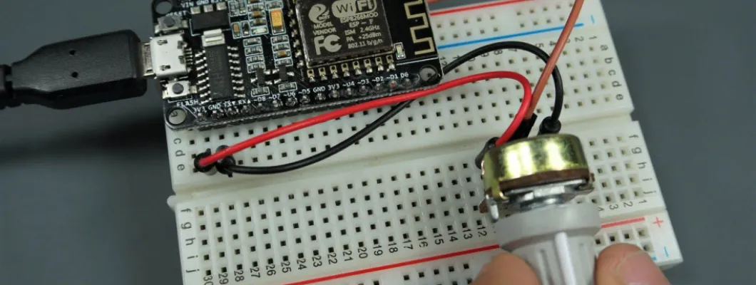
Both ESP8266-12E and ESP8266-07 have one ADC pin that is easily accessible. This means that those ESP8266 boards can read analog signals. In this tutorial we’ll show you how to use analog reading with the ESP8266 using Arduino IDE, MicroPython or Lua firmware.

As an example, we’ll show you how to read analog values from a potentiometer. This post is divided in three sections:
- ESP8266 Analog Read with Arduino IDE
- ESP8266 Analog Read with MicroPython
- ESP8266 Analog Read with Lua/NodeMCU
ESP8266 ADC Specifications
When referring to the ESP8266 ADC pin you will often hear these different terms interchangeably:
- ADC (Analog-to-digital Converter)
- TOUT
- Pin6
- A0
- Analog Pin 0
All these terms refer to the same pin in the ESP8266 that is highlighted in the next section.
ESP8266 ADC Resolution
The ADC pin has a 10-bit resolution, which means you’ll get values between 0 and 1023.
ESP8266 Input Voltage Range
The ESP8266 ADC pin input voltage range is 0 to 1V if you’re using the bare chip. However, most ESP8266 development boards come with an internal voltage divider, so the input range is 0 to 3.3V. So, in sumary:
- ADC Voltage range in ESP8266 development boards: 0 to 3.3V (for example: ESP8266 12-E NodeMCU Kit, WeMos D1 Mini, …)
- ADC Voltage range in ESP8266 chip: 0 to 1V (for example: ESP-07 chip, ESP-12E chip, …)
ESP8266 NodeMCU Analog Pin
With the ESP8266 12-E NodeMCU kit and other ESP8266 development boards, it is very easy to access the A0, you simply connect a jumper wire to the pin (see figure below).
If you’re using an ESP8266 chip, like the ESP8266-07, you need to solder a wire to that pin.
Parts Required
To show you how to use analog reading with the ESP8266, we’ll read the values from a potentiometer. For that, you need to wire a potentiometer to your board.
Here’s the hardware that you need to complete this tutorial:
- Recommended: ESP8266-12E NodeMCU Kit (read ESP8266 development boards comparison)
- Alternative: 1x ESP8266-07 chip or 1x ESP8266-12E chip + FTDI Programmer
- 100 Ohm Resistor (needed if you’re using a bare chip)
- 220 Ohm Resistor(needed if you’re using a bare chip)
- 1k Ohm Potentiometer
- Breadboard
- Jumper wires
You can use the preceding links or go directly to MakerAdvisor.com/tools to find all the parts for your projects at the best price!
Schematic Diagram
If you’re using an ESP8266 development board, follow the next schematic diagram.

If you’re using an ESP8266 chip with input voltage range of 0V to 1V, you need to make sure that the input voltage on the A0 pin doesn’t exceed 1V. So, you need a voltage divider circuit, as shown below.

We’re using a 100 Ohm and a 220 Ohm resistor, so that the Vout is 1V.

Recommend reading: ESP8266 Pinout Reference: Which GPIO pins should you use?
1. ESP8266 NodeMCU Analog Read with Arduino IDE
This section shows how to read analog values with the ESP8266 using Arduino IDE.
Install ESP8266 in Arduino IDE
In order to upload code to your ESP8266, you need to install the ESP8266 add-on first, if you haven’t already. Follow the next tutorial:
Code
Copy the following code to your Arduino IDE.
/*********
  Rui Santos
  Complete project details at https://randomnerdtutorials.com
*********/

const int analogInPin = A0;  // ESP8266 Analog Pin ADC0 = A0

int sensorValue = 0;  // value read from the pot

void setup() {
  // initialize serial communication at 115200
  Serial.begin(115200);
}

void loop() {
  // read the analog in value
  sensorValue = analogRead(analogInPin);

  // print the readings in the Serial Monitor
  Serial.print("sensor = ");
  Serial.print(sensorValue);

  delay(1000);
}
The code starts by declaring the ESP8266 analog pin in the analogInPin variable:
const int analogInPin = A0; // ESP8266 Analog Pin ADC0 = A0The potentiometer value will be stored on the sensorValue variable:
int sensorValue = 0; // value read from the potIn the setup(), initialize the Serial Monitor for debugging purposes:
void setup() {
  // initialize serial communication at 115200
  Serial.begin(115200);
}
In the loop(), we read the analog value by using the analogRead() function and passing the analogInPin as an argument. The value is saved on the sensorValue variable:
sensorValue = analogRead(analogInPin);Finally, the readings are displayed on the Serial Monitor, so that you can actually see what is going on.
Serial.print(sensorValue);Uploading the Code
Upload the previous code to the ESP8266. Make sure you have the right board and COM port select. Go to Tools> Board and select the ESP8266 model you’re using. In our case, we’re using the ESP8266 12-E NodeMCU Kit.

Go to Tools > Port and select the COM port the ESP8266 is connected to.

Press the Arduino IDE upload button.
Note: if you’re using an ESP-07 or ESP-12E chip, you need an FTDI programmer to upload code.
Demonstration
After uploading the code, open the Serial Monitor at a baud rate of 115200. The analog readings should be displayed.

Rotate the potentiometer and see the values increasing or decreasing.
2. ESP8266 NodeMCU Analog Read with MicroPython
This section show how to read analog values with the ESP8266 using MicroPython firmware.
To follow this tutorial you need MicroPython firmware installed in your ESP8266 board. You also need an IDE to write and upload the code to your board. We suggest using Thonny IDE or uPyCraft IDE:
- Thonny IDE:
- uPyCraft IDE:
- Install uPyCraft IDE (Windows, Mac OS X, Linux)
- Flash/Upload MicroPython Firmware to ESP32 and ESP8266
Script – Analog Reading ESP82266
The following script for the ESP8266 reads analog values from A0 pin.
# Complete project details at https://RandomNerdTutorials.com/micropython-programming-with-esp32-and-esp8266/

from machine import Pin, ADC
from time import sleep

pot = ADC(0)

while True:
  pot_value = pot.read()
  print(pot_value)
  sleep(0.1)
How the code works
To read analog inputs, import the ADC class in addition to the Pin class from the machine module. We also import the sleep method.
from machine import Pin, ADC
from time import sleep
Then, create an ADC object called pot on A0 pin.
pot = ADC(0)In the loop, read the pot value and save it in the pot_value variable. To read the value from the pot, use the read() method on the pot object.
pot_value = pot.read()Then, print the pot_value.
print(pot_value)At the end, add a delay of 100 ms.
sleep(0.1)In summary:
- To read an analog value you use the ADC class;
- To create an ADC object simply call ADC(0).
- To read the analog value, use the read() method on the ADC object.
Demonstration
After uploading the code to the ESP8266 board using Thonny IDE or uPyCraft IDE, rotate the potentiometer.
Check the shell of your MicroPython IDE to read the values from the potentiometer.

3. ESP8266 Analog Read with Lua/NodeMCU
This section shows how use the NodeMCU firmware to read analog values with the ESP8266.
Flashing ESP8266 with Lua/NodeMCU firmware
First, you have to flash your ESPs with NodeMCU firmare.
I recommend using the ESPlorer IDE which is a program created by 4refr0nt to send commands to your ESP8266.
Follow these instructions to download and install ESPlorer IDE:
- Click here to download ESPlorer
- Unzip that folder
- Go to the main folder
- Run ESPlorer.jar
- Open the ESPlorer
Testing the ADC Pin (A0)
To send commands with the ESPlorer IDE, you need to establish a serial communication with your ESP, follow these instructions:
- Connect your ESP-12E or FTDI programmer to your computer
- Set bad raute as 9600
- Select your ESP-12E or FTDI programmer port (COM3, for example)
- Press Open/Close

Then type the following command:
print(adc.read(0))Click the button “Send” as shown below.

It should return a value between 0 and 1024. Rotate your potentiometer and send the print(adc.read(0)) command a few more times to get the potentiometer value.
When your potentiometer is near 0V it prints 0 and when it reaches 3.3V it should print 1024.
Wrapping Up
In this tutorial we’ve shown you how to read analog values using the ESP8266 analog pin (A0). One important thing to notice is that the ESP8266 analog input range is either 0-1V if you’re using a bare chip, or 0-3.3V if you’re using a development board.
Either way, you should always be careful not to exceed the maximum recommended voltage. You may consider adding a voltage divider circuit when you need a higher input voltage range.
We hope you’ve found this tutorial useful. If you’re just getting started with the ESP8266, we recommend the following resources:
- Home Automation Using ESP8266 (eBook)
- Getting Started with the ESP8266
- ESP8266 GPIO Reference Guide
- ESP8266 Web Server
Thanks for reading.





Comment