We can use Arduino IDE to write the MPPT Solar Charge Controller Project Code. The code has all the parameters and functions to measure Solar Panel Voltage, Current, Power, Battery Voltage, Charger state, SOC, PWM duty cycle, load status. The 20×4 LCD Display will show the real-time status of this parameters.
Copy the following code and upload it to the Arduino Nano Board.
#include "TimerOne.h"
#include <LiquidCrystal_I2C.h>
#include <Wire.h>
#define ENABLE_DATALOGGER 0
#define LOAD_ALGORITHM 1
#define SOL_AMPS_CHAN 1
#define SOL_VOLTS_CHAN 0
#define BAT_VOLTS_CHAN 2
#define AVG_NUM 8
// #define SOL_AMPS_SCALE 0.026393581
#define SOL_VOLTS_SCALE 0.029296875
#define BAT_VOLTS_SCALE 0.029296875
#define PWM_PIN 6
#define PWM_ENABLE_PIN 5
#define PWM_FULL 1023
#define PWM_MAX 100
#define PWM_MIN 60
#define PWM_START 90
#define PWM_INC 1
#define TRUE 1
#define FALSE 0
#define ON TRUE
#define OFF FALSE
#define TURN_ON_MOSFETS digitalWrite(PWM_ENABLE_PIN, HIGH)
#define TURN_OFF_MOSFETS digitalWrite(PWM_ENABLE_PIN, LOW)
#define ONE_SECOND 50000
#define LOW_SOL_WATTS 5.00
#define MIN_SOL_WATTS 0.10
#define MIN_BAT_VOLTS 11.00
#define MAX_BAT_VOLTS 14.10
#define BATT_FLOAT 13.60
#define HIGH_BAT_VOLTS 13.00
#define LVD 11.5
#define OFF_NUM 9
#define LED_YELLOW 12
#define LED_GREEN 11
#define LED_RED 10
#define LOAD_PIN 4
#define BACK_LIGHT_PIN 3
float AcsValue, ss = 0.0;
byte battery_icons[6][8] =
{{
0b01110,
0b11011,
0b10001,
0b10001,
0b10001,
0b10001,
0b10001,
0b11111,
},
{
0b01110,
0b11011,
0b10001,
0b10001,
0b10001,
0b10001,
0b11111,
0b11111,
},
{
0b01110,
0b11011,
0b10001,
0b10001,
0b10001,
0b11111,
0b11111,
0b11111,
},
{
0b01110,
0b11011,
0b10001,
0b11111,
0b11111,
0b11111,
0b11111,
0b11111,
},
{
0b01110,
0b11011,
0b11111,
0b11111,
0b11111,
0b11111,
0b11111,
0b11111,
},
{
0b01110,
0b11111,
0b11111,
0b11111,
0b11111,
0b11111,
0b11111,
0b11111,
}
};
#define SOLAR_ICON 6
byte solar_icon[8] =
{
0b11111,
0b10101,
0b11111,
0b10101,
0b11111,
0b10101,
0b11111,
0b00000
};
#define PWM_ICON 7
byte _PWM_icon[8] =
{
0b11101,
0b10101,
0b10101,
0b10101,
0b10101,
0b10101,
0b10101,
0b10111,
};
byte backslash_char[8] =
{
0b10000,
0b10000,
0b01000,
0b01000,
0b00100,
0b00100,
0b00010,
0b00010,
};
float sol_amps;
float sol_volts;
float bat_volts;
float sol_watts;
float old_sol_watts = 0;
unsigned int seconds = 0;
unsigned int prev_seconds = 0;
unsigned int interrupt_counter = 0;
unsigned long time = 0;
int delta = PWM_INC;
int pwm = 0;
int back_light_pin_State = 0;
boolean load_status = false;
enum charger_mode {off, on, bulk, bat_float} charger_state;
LiquidCrystal_I2C lcd(0x27, 20, 4);
void setup()
{
pinMode(PWM_ENABLE_PIN, OUTPUT);
TURN_OFF_MOSFETS;
charger_state = off;
lcd.init();
lcd.backlight();
for (int batchar = 0; batchar < 6; ++batchar)
{
lcd.createChar(batchar, battery_icons[batchar]);
}
lcd.createChar(PWM_ICON, _PWM_icon);
lcd.createChar(SOLAR_ICON, solar_icon);
lcd.createChar('\\', backslash_char);
pinMode(LED_RED, OUTPUT);
pinMode(LED_GREEN, OUTPUT);
pinMode(LED_YELLOW, OUTPUT);
Timer1.initialize(20);
Timer1.pwm(PWM_PIN, 0);
Timer1.attachInterrupt(callback);
Serial.begin(9600);
pwm = PWM_START;
pinMode(BACK_LIGHT_PIN, INPUT);
pinMode(LOAD_PIN, OUTPUT);
digitalWrite(LOAD_PIN, LOW);
digitalWrite(BACK_LIGHT_PIN, LOW);
lcd.setCursor(0, 0);
lcd.print("SOL");
lcd.setCursor(4, 0);
lcd.write(SOLAR_ICON);
lcd.setCursor(8, 0);
lcd.print("BAT");
}
void loop()
{
read_data();
run_charger();
print_data();
load_control();
led_output();
lcd_display();
}
int read_adc(int channel)
{
int sum = 0;
int temp;
int i;
for (i = 0; i < AVG_NUM; i++)
{
temp = analogRead(channel);
sum += temp;
delayMicroseconds(50);
}
return (sum / AVG_NUM);
}
float read_adccc()
{
int i;
float AcsValue, ss = 0.0;
for (i = 0; i < AVG_NUM; i++)
{
AcsValue = analogRead(A1);
ss += mapf(AcsValue, 510, 580, 0.0, 5.0);
delayMicroseconds(50);
}
Serial.println(AcsValue);
Serial.println(ss / AVG_NUM);
return (ss / AVG_NUM);
}
void read_data(void)
{
sol_amps = read_adccc();
sol_volts = read_adc(SOL_VOLTS_CHAN) * SOL_VOLTS_SCALE;
bat_volts = read_adc(BAT_VOLTS_CHAN) * BAT_VOLTS_SCALE;
sol_watts = sol_amps * sol_volts ;
}
void callback()
{
if (interrupt_counter++ > ONE_SECOND)
{
interrupt_counter = 0;
seconds++;
}
}
void set_pwm_duty(void)
{
if (pwm > PWM_MAX) {
pwm = PWM_MAX;
}
else if (pwm < PWM_MIN) {
pwm = PWM_MIN;
}
if (pwm < PWM_MAX) {
Timer1.pwm(PWM_PIN, (PWM_FULL * (long)pwm / 100), 20);
}
else if (pwm == PWM_MAX) {
Timer1.pwm(PWM_PIN, (PWM_FULL - 1), 20);
}
}
void run_charger(void)
{
static int off_count = OFF_NUM;
switch (charger_state)
{
case on:
if (sol_watts < MIN_SOL_WATTS)
{
charger_state = off;
off_count = OFF_NUM;
TURN_OFF_MOSFETS;
}
else if (bat_volts > (BATT_FLOAT - 0.1))
{
charger_state = bat_float;
}
else if (sol_watts < LOW_SOL_WATTS) {
pwm = PWM_MAX;
set_pwm_duty();
}
else {
pwm = ((bat_volts * 10) / (sol_volts / 10)) + 5;
charger_state = bulk;
}
break;
case bulk:
if (sol_watts < MIN_SOL_WATTS)
{
charger_state = off;
off_count = OFF_NUM;
TURN_OFF_MOSFETS;
}
else if (bat_volts > BATT_FLOAT)
{
charger_state = bat_float;
}
else if (sol_watts < LOW_SOL_WATTS)
{
charger_state = on;
TURN_ON_MOSFETS;
}
else {
if (old_sol_watts >= sol_watts)
{
delta = -delta;
}
pwm += delta;
old_sol_watts = sol_watts;
set_pwm_duty();
}
break;
case bat_float:
if (sol_watts < MIN_SOL_WATTS)
{
charger_state = off;
off_count = OFF_NUM;
TURN_OFF_MOSFETS;
set_pwm_duty();
}
else if (bat_volts > BATT_FLOAT)
{
TURN_OFF_MOSFETS;
pwm = PWM_MAX;
set_pwm_duty();
}
else if (bat_volts < BATT_FLOAT)
{
pwm = PWM_MAX;
set_pwm_duty();
TURN_ON_MOSFETS;
if (bat_volts < (BATT_FLOAT - 0.1))
{
charger_state = bulk;
}
}
break;
case off:
TURN_OFF_MOSFETS;
if (off_count > 0)
{
off_count--;
}
else if ((bat_volts > BATT_FLOAT) && (sol_volts > bat_volts)) {
charger_state = bat_float;
TURN_ON_MOSFETS;
}
else if ((bat_volts > MIN_BAT_VOLTS) && (bat_volts < BATT_FLOAT) && (sol_volts > bat_volts)) {
charger_state = bulk;
TURN_ON_MOSFETS;
}
break;
default:
TURN_OFF_MOSFETS;
break;
}
}
void load_control()
{
#if LOAD_ALGORITHM == 0
load_on(sol_watts < MIN_SOL_WATTS && bat_volts > LVD);
#else
load_on(sol_watts > MIN_SOL_WATTS && bat_volts > BATT_FLOAT);
#endif
}
void load_on(boolean new_status)
{
if (load_status != new_status)
{
load_status = new_status;
digitalWrite(LOAD_PIN, new_status ? HIGH : LOW);
}
}
void print_data(void)
{
Serial.print(seconds, DEC);
Serial.print(" ");
Serial.print("Charging = ");
if (charger_state == on) Serial.print("on ");
else if (charger_state == off) Serial.print("off ");
else if (charger_state == bulk) Serial.print("bulk ");
else if (charger_state == bat_float) Serial.print("float");
Serial.print(" ");
Serial.print("pwm = ");
if (charger_state == off)
Serial.print(0, DEC);
else
Serial.print(pwm, DEC);
Serial.print(" ");
Serial.print("Current (panel) = ");
Serial.print(sol_amps);
Serial.print(" ");
Serial.print("Voltage (panel) = ");
Serial.print(sol_volts);
Serial.print(" ");
Serial.print("Power (panel) = ");
Serial.print(sol_volts);
Serial.print(" ");
Serial.print("Battery Voltage = ");
Serial.print(bat_volts);
Serial.print(" ");
Serial.print("\n\r");
}
void light_led(char pin)
{
static char last_lit;
if (last_lit == pin)
return;
if (last_lit != 0)
digitalWrite(last_lit, LOW);
digitalWrite(pin, HIGH);
last_lit = pin;
}
void led_output(void)
{
static char last_lit;
if (bat_volts > 14.1 )
light_led(LED_YELLOW);
else if (bat_volts > 11.9)
light_led(LED_GREEN);
else
light_led(LED_RED);
}
void lcd_display()
{
static bool current_backlight_state = -1;
back_light_pin_State = digitalRead(BACK_LIGHT_PIN);
if (current_backlight_state != back_light_pin_State) {
current_backlight_state = back_light_pin_State;
if (back_light_pin_State == HIGH)
lcd.backlight();
else
lcd.noBacklight();
}
if (back_light_pin_State == HIGH)
{
time = millis();
}
lcd.setCursor(0, 1);
lcd.print(sol_volts);
lcd.print("V ");
lcd.setCursor(0, 2);
lcd.print(sol_amps);
lcd.print("A");
lcd.setCursor(0, 3);
lcd.print(sol_watts);
lcd.print("W ");
lcd.setCursor(8, 1);
lcd.print(bat_volts);
lcd.setCursor(8, 2);
if (charger_state == on)
lcd.print("on ");
else if (charger_state == off)
lcd.print("off ");
else if (charger_state == bulk)
lcd.print("bulk ");
else if (charger_state == bat_float)
{
lcd.print(" ");
lcd.setCursor(8, 2);
lcd.print("float");
}
int pct = 100.0 * (bat_volts - 11.3) / (12.7 - 11.3);
if (pct < 0)
pct = 0;
else if (pct > 100)
pct = 100;
lcd.setCursor(12, 0);
lcd.print((char)(pct * 5 / 100));
lcd.setCursor(8, 3);
pct = pct - (pct % 10);
lcd.print(pct);
lcd.print("% ");
lcd.setCursor(15, 0);
lcd.print("PWM");
lcd.setCursor(19, 0);
lcd.write(PWM_ICON);
lcd.setCursor(15, 1);
lcd.print(" ");
lcd.setCursor(15, 1);
if ( charger_state == off)
lcd.print(0);
else
lcd.print(pwm);
lcd.print("% ");
lcd.setCursor(15, 2);
lcd.print("Load");
lcd.setCursor(15, 3);
if (load_status)
{
lcd.print("On ");
}
else
{
lcd.print("Off ");
}
spinner();
backLight_timer();
}
void backLight_timer()
{
if ((millis() - time) <= 15000)
lcd.backlight();
else
lcd.noBacklight();
}
void spinner(void)
{
static int cspinner;
static char spinner_chars[] = { '*', '*', '*', ' ', ' '};
cspinner++;
lcd.print(spinner_chars[cspinner % sizeof(spinner_chars)]);
}
float mapf(float x, float in_min, float in_max, float out_min, float out_max) {
return (x - in_min) * (out_max - out_min) / (in_max - in_min) + out_min;
}
Now let us do the final testing of our Arduino MPPT Solar Charge Controller project and find out how efficient it is.
Initially you need to calibrate the ACS712 Current Sensor so that it can measure the current accurately. The ACS712 sensor reads the current value and converts it into a relevant voltage value. You can download the ACS712 Calibration Code if you want to calibrate the sensor.
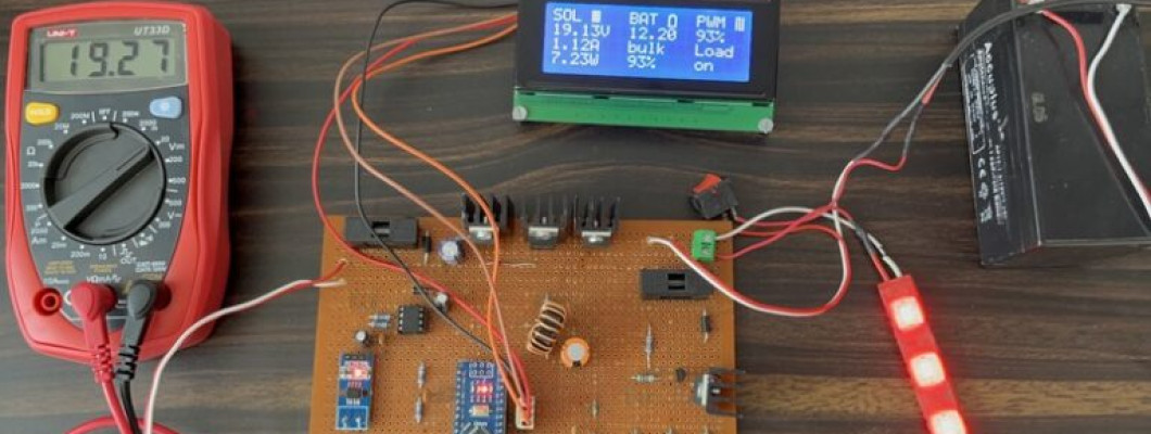
In case you are okay with the calibration then you can upload the main source code above. After uploading the code, the LCD will display the following parameters.
The LCD will display all the voltages as 0 as, we didn’t connect the Solar Panel, Load, Battery currently.
If we expose Solar Panel outside, it gives a voltage of almost 20V.
When we connect the Solar Panel to the input terminal of the circuit, the LCD will display the value of Solar panel voltage, Current and Power in the first column.
When we connect the Battery to the circuit, the LCD will display Battery Voltage, Charger state, and SOC in the 2nd column.
At last, we can connect any load to the load terminal for testing the status. The LCD will show the PWM duty cycle and load status on the 3rd column.
The Red, Green and Yellow LEDs are used to indicate the battery voltage level.
While testing we can notice that the voltage to the solar panel increases initially, if the output power increase, the voltage continually increases until the output power starts decreasing. Once the output power starts decreasing, the voltage to the solar panel decreases until it reaches maximum power. This process is continued until the MPPT is attained. This result is an oscillation of the output power around the MPP.
This is how you can design and develop your own MPPT Solar Charge Controller using Arduino. We can do a lot of modifications and design the circuit with additional features to increase efficiency with better results.










Comment