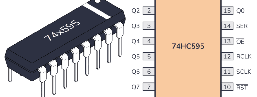
The 74HC595 is an integrated circuit featuring an 8-bit shift register and a storage register with tri-state parallel outputs. It converts serial input into parallel output, allowing you to conserve MCU I/O pins.
When MR (pin 10) is set to high level and OE (pin 13) is set to low level, data is clocked into the shift register on the rising edge of SHcp and transferred to the storage register on the rising edge of STcp.
If the two clock signals are connected, the shift register will always operate one clock pulse ahead of the storage register.
The shift register includes a serial input pin (Ds), a serial output pin (Q7’), and an asynchronous reset (active low).
The storage register outputs an 8-bit parallel bus in three states.
When OE is enabled (low level), the data stored in the storage register is output to the parallel bus (Q0 ~ Q7).

Pins of 74HC595 and their functions:
Q0-Q7: 8-bit parallel data output pins, able to control 8 LEDs or 8 pins of 7-segment display directly.
Q7’: Series output pin, connected to DS of another 74HC595 to connect multiple 74HC595s in series
MR: Reset pin, active at low level;
SHcp: Time sequence input of shift register. On the rising edge, the data in shift register moves successively one bit, i.e. data in Q1 moves to Q2, and so forth. While on the falling edge, the data in shift register remain unchanged.
STcp: Time sequence input of storage register. On the rising edge, data in the shift register moves into memory register.
CE: Output enable pin, active at low level.
DS: Serial data input pin
VCC: Positive supply voltage.
GND: Ground.
Let us learn how to use the 74HC595 shift register to control multiple LEDs with just a few GPIO pins on the Raspberry Pi Pico 2 W. The 74HC595 is an integrated circuit (IC) that allows you to expand the number of digital outputs using a serial input. This is incredibly useful when you want to control many outputs but have limited GPIO pins available.
Required Components
In this project, we need the following components.
It’s definitely convenient to buy a whole kit, here’s the link:
You can also buy them separately from the links below.
SN
COMPONENT INTRODUCTION
QUANTITY
PURCHASE LINK
1
Pico 2 W or Pico W
1
BUY 2
Micro USB Cable
1
BUY 3
Breadboard 1
4
Jumper wires
Assorted
5
RESISTOR 8(220Ω)
6
LED 8
7
74HC595 1
Understanding the 74HC595 Shift Register
The 74HC595 is an 8-bit serial-in, parallel-out shift register with output latches. It has the ability to take serial data input and convert it into parallel output, allowing you to control 8 outputs using only 3 GPIO pins from the Pico.
Key Pins on the 74HC595:

DS (Pin 14): Serial Data Input
SHCP (Pin 11): Shift Register Clock Input
STCP (Pin 12): Storage Register Clock Input (Latch Pin)
OE (Pin 13): Output Enable (Active Low, connect to GND)
MR (Pin 10): Master Reset (Active Low, connect to 3.3V)
Q0-Q7 (Pins 15, 1-7): Parallel Outputs
VCC (Pin 16): Connect to 3.3V
GND (Pin 8): Connect to GND
Schematic

Wiring
Writing the Code
We’ll write a program that controls the LEDs connected to the 74HC595 shift register by sending serial data from the Pico. The LEDs will light up one after another in a sequence.
Note
You can open the file
5.1_microchip_74hc595.inounder the path ofpico-2w-kit-main/arduino/5.1_microchip_74hc595.Or copy this code into Arduino IDE.
Don’t forget to select the board(Raspberry Pi Pico) and the correct port before clicking the Upload button.
// Define the pins connected to the 74HC595
const int DS = 0;   // GPIO 0 -> DS (Pin 14)
const int SHCP = 1; // GPIO 1 -> SHCP (Pin 11)
const int STCP = 2; // GPIO 2 -> STCP (Pin 12)

// Array of binary patterns to control LEDs
int datArray[] = {
  0b00000000, // All LEDs off
  0b00000001, // LED 0 on
  0b00000011, // LEDs 0 and 1 on
  0b00000111, // LEDs 0, 1, and 2 on
  0b00001111, // LEDs 0, 1, 2, and 3 on
  0b00011111, // LEDs 0 to 4 on
  0b00111111, // LEDs 0 to 5 on
  0b01111111, // LEDs 0 to 6 on
  0b11111111  // All LEDs on
};

void setup() {
  // Initialize the control pins as outputs
  pinMode(DS, OUTPUT);
  pinMode(SHCP, OUTPUT);
  pinMode(STCP, OUTPUT);
}

void loop() {
  // Iterate through each pattern in datArray
  for (int num = 0; num < 9; num++) {
    // Set STCP to LOW to prepare for data
    digitalWrite(STCP, LOW);

    // Shift out the data to the shift register
    shiftOut(DS, SHCP, MSBFIRST, datArray[num]);

    // Set STCP to HIGH to latch the data to the output pins
    digitalWrite(STCP, HIGH);

    delay(500); // Wait for half a second before the next pattern
  }

  // Turn off all LEDs after the sequence
  digitalWrite(STCP, LOW);
  shiftOut(DS, SHCP, MSBFIRST, 0b00000000);
  digitalWrite(STCP, HIGH);
  delay(500);
}
After uploading the code, the LEDs connected to the 74HC595 should light up one after another, following the patterns defined in
datArray. After all LEDs are turned on, they will turn off in sequence.Understanding the Code
Defining Control Pins:
DS (Data Serial Input): Receives the serial data.SHCP (Shift Register Clock Input): Controls the shifting of data into the register.STCP (Storage Register Clock Input): Controls the latching of data to the output pins.
const int DS = 0;   // GPIO 0 -> DS (Pin 14)
const int SHCP = 1; // GPIO 1 -> SHCP (Pin 11)
const int STCP = 2; // GPIO 2 -> STCP (Pin 12)
Creating Data Patterns:
An array
datArrayholds different binary patterns to control the LEDs.Each bit represents the state of an LED (1 for on, 0 for off).
int datArray[] = {
  0b00000000, // All LEDs off
  0b00000001, // LED 0 on
  0b00000011, // LEDs 0 and 1 on
  0b00000111, // LEDs 0, 1, and 2 on
  0b00001111, // LEDs 0, 1, 2, and 3 on
  0b00011111, // LEDs 0 to 4 on
  0b00111111, // LEDs 0 to 5 on
  0b01111111, // LEDs 0 to 6 on
  0b11111111  // All LEDs on
};
Setup Function:
Sets the
DS,SHCP, andSTCPpins as outputs to send data to the shift register.void setup() { // Initialize the control pins as outputs pinMode(DS, OUTPUT); pinMode(SHCP, OUTPUT); pinMode(STCP, OUTPUT); }
Loop Function: The
forloop cycles through each pattern in thedatArrayarray.Shifting Out Data:
shiftOutsends the byte of data one bit at a time.MSBFIRSTindicates that the most significant bit is sent first.
shiftOut(DS, SHCP, MSBFIRST, datArray[num]);
Latching Data:
Setting
STCPLOWprepares the shift register for new data.After shifting out the data, setting
STCPHIGHlatches the data to the output pins, updating the LED states.
digitalWrite(STCP, LOW);
// shiftOut(...)
digitalWrite(STCP, HIGH);
Delay:
delay(500);adds a half-second pause between each pattern for visibility.Turning Off LEDs:
After cycling through all patterns, turns off all LEDs by sending 0b00000000.
digitalWrite(STCP, LOW);
shiftOut(DS, SHCP, MSBFIRST, 0b00000000);
digitalWrite(STCP, HIGH);
delay(500);
Troubleshooting
No LEDs Lighting Up:
Check all wiring connections.
Ensure the 74HC595 is properly powered.
Verify that the GPIO pins on the Pico are correctly connected to the shift register.
Incorrect LED Behavior:
Double-check the binary patterns in
datArray.Ensure that the resistors are correctly placed to limit current to the LEDs.
Further Exploration
Controlling Other Devices:
Use the 74HC595 to control relays, motors, or other high-power devices.
Chaining Shift Registers:
Connect multiple 74HC595s in series to control even more outputs with the same three GPIO pins.
Creating LED Patterns:
Design and implement more complex LED animations and patterns by modifying the datArray.
Integrating with Sensors:
Combine the shift register with various sensors to create responsive and interactive systems.
Building a LED Matrix Display:
Use multiple shift registers to build a larger LED matrix for displays or signage.
Conclusion
In this blog, you’ve learned how to use the 74HC595 shift register with the Raspberry Pi Pico to control multiple LEDs using just three GPIO pins. This technique allows you to expand the number of digital outputs, enabling more complex and interactive projects without the need for additional GPIO resources. By understanding how to send serial data and latch it into parallel outputs, you can efficiently manage multiple actuators, displays, or other peripherals in your electronics projects.






Comment