


Learners! Today, we're about to embark on an exciting journey into the realm of flashing firmware to an ESP8266-01 and connecting it to Blynk using the ESP8266-01 as an Arduino WiFi shield. This tutorial will serve as your guide, and I'll be your teacher, leading you through each step of the process.
Hardware Needed:
- Arduino Uno/Mega
- Jumper wires
- USB A to USB B cable
- ESP8266-01
- Linux or Mac for flashing firmware
- Arduino IDE (Download)
- Most recent Blynk library (GitHub Link)
- Blynk_v0.3.4.zip (Download)
- pySerial (Download)
- ESP8266 Blynk library (GitHub Link)
- esptool (GitHub Link)
- Sdk1.0.0 v0.22 ESP8266 firmware (Download)
- esp8266_flasher (GitHub Link) - For Windows only
- Blynk app on iPhone or Android
Step 1: Download These Files
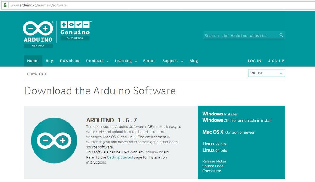


*Download Arduino IDE
*Download most recent Blynk library
*Download the Blynk-ESP8266 library
Click the link provided, download and install the library.
*Download pySerial
Click the link provided in the intro and click what is in the red box. Make sure you move it to your desktop. Once it's there, double click the "pyserial-2.7.tar.gz" file and it will create a pyserial-2.7 folder.
*Download esptool
Click the link provided in the intro and click what is in the red box. Make sure you move it to your desktop.
*Download Sdk1.0.0 v0.22 ESP8266 firmware
This will download just by clicking the link in the intro page. Make sure you move it to your desktop. Open the "esptool-master" folder and move the "AT22SDK100-2015-03-20-boot12.bin" file into it. Then, rename it to "AT22SDK10020150320boot12.bin".
*Download esp8266_flasher [For Windows]
Download esp8266_flasher.exe
Step 2: Using Windows:


*Connect your arduino to your computer using an USB 2.0 cable.
- *ESP8266:____________ Arduino:
- GND -------------------------- GND
- GP2 -------------------------- Not connected
- GP0 -------------------------- GND
- RXD -------------------------- RX
- TXD -------------------------- TX
- CHPD ------------------------ 3.3V
- RST -------------------------- Not connected
- VCC -------------------------- 3.3V
*Open "esp8266_flasher.exe" and click on bin.
*Select the binary file "AT22SDK100-2015-03-20-boot12.bin".
*Enter proper COM port. In this case it is COM3
*Then click on download button,
*If your connections are proper the flashing will begin after erasing flash memory.
*After completion it shows "failed to leave flash mode this is OK.
Step 3: Using Linux: Changing the Directory
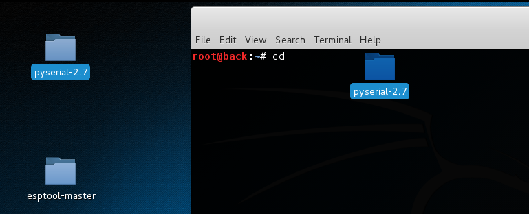
Open your Terminal (here we are using Kali linux), then type "cd". Next, drag the "pyserial-2.7" folder into the terminal window and hit enter.
Step 4: Installing PySerial
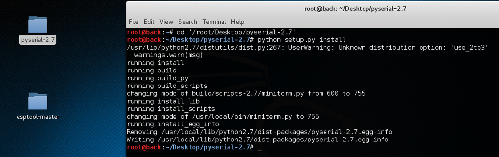
Enter this command “python setup.py install" into the terminal
(If your terminal doesn’t have root/administrator/Superuser privilege access use "sudo python setup.py install" and enter password when asked.)
Step 5: Connecting Arduino and ESP8266-01
*Connect your arduino to your computer using an USB 2.0 cable.
*ESP8266:____________ Arduino:
GND -------------------------- GND
GP2 -------------------------- Not connected
GP0 -------------------------- GND
RXD -------------------------- RX
TXD -------------------------- TX
CHPD ------------------------ 3.3V
RST -------------------------- Not connected
VCC -------------------------- 3.3V
Step 6: Flashing the Firmware to ESP8266-01


*Type "cd". Next, drag the "esptool-master" folder into the terminal window and hit enter.
* Esptool-master should contain following files
[ AT22SDK10020150320boot12.bin, esptool.py, LICENCE, MANIFEST.in, README.md, setup.py ]
*Enter this command
"sudo python esptool.py --port /dev/ttyACM0 write flash 0x00000 AT22SDK10020150320boot12.bin"
Note:The port address of your arduino may be different. You can use the command “ls /dev/tty*” to list all devices.
Step 7: Add the Blynk Library and the Blynk-ESP8266 Library to Your Arduino IDE.
*Arduino IDE >> Sketch >> Include library >> Add .zip library.
* And install "blynk-library-master" and "ITEADLIB_Arduino_WeeESP8266-master" libraries.
*Update the ESP8266 library from “Arduino IDE >> Sketch >> Include library >> manage library”.
Step 8: Uploading the Code to Arduino
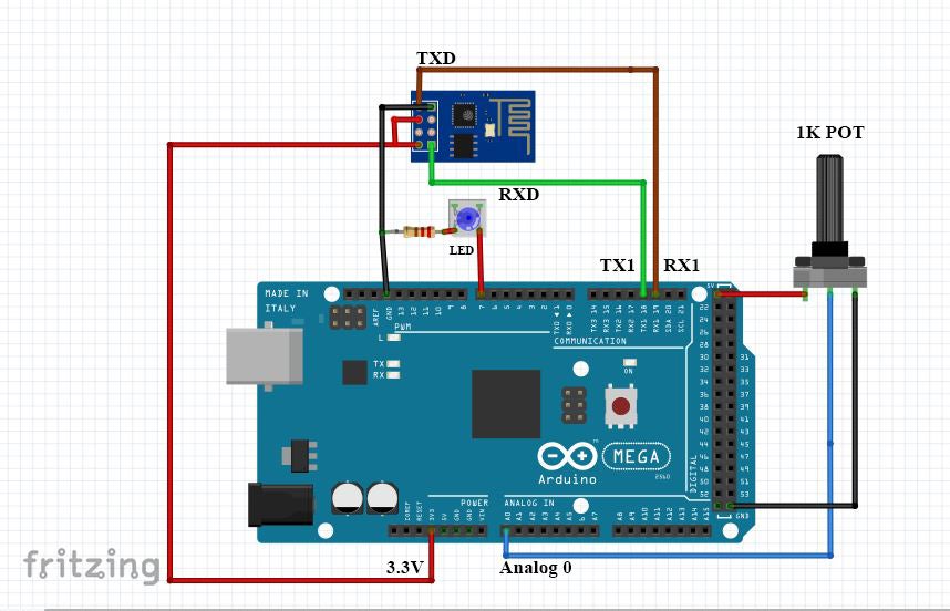
- USING Arduino MEGA:
ESP8266:____________ Arduino:
GND -------------------------- GND
GP2 -------------------------- Not connected
GP0 -------------------------- Not connected
RXD -------------------------- TX
TXD -------------------------- RX
CHPD ------------------------ 3.3V
RST -------------------------- Not connected
VCC -------------------------- 3.3V
We will be using a 1K POT connected to analog0 pin and an LED connected to D7 of arduino mega.
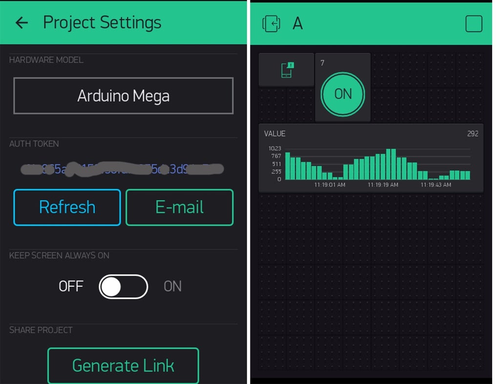
*Open Your “Blynk app” from android/iPhone get the “authentication token”.
- Open the code in “Arduino IDE >> File >>examples >> blynk >> BoardsAndShields>> ESP8266_Shield_HardSer”
- Add your authentication token to the code
- Enter "SSID" and "PASSWORD" in respective fields.
- Upload the code to your arduino.
Step 9: Connecting, Controlling and Monitoring Arduino Pins Using Blynk App
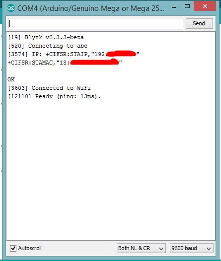
In the Serial monitor you can see that the connection has been established with blynk server.
Here’s the screenshot of the blynk app
Digital Pin 7 of Arduino mega --------->>controlled by blynk app.
Analog Pin 0 data from Pot -------- >> displayed on graph.
Step 10: USING ARDUINO UNO
Similarly you can also use arduino uno....
ESP8266:____________Arduino:
GND -------------------------- GND
GP2 -------------------------- Not connected
GP0 -------------------------- Not connected
RXD -------------------------- D3 (SoftwareSerial)
TXD -------------------------- D2 (SoftwareSerial)
CHPD ------------------------ 3.3V
RST -------------------------- Not connected
VCC -------------------------- 3.3V
For Arduino UNO you can use “Arduino IDE >> File >> examples >> blynk >> BoardsAndShields>> ESP8266_Shield_SoftSer”
*The “Baud rate” of ESP8266 has to be changed to 9600 in Software Serial.
*AT command “AT+UART_DEF=9600,8,1,0,0”.

Comment