


Overview
In this project we are going to build our own MPPT Solar Charge Controller using Arduino and by combining many active-passive electronics. MPPT means Maximum Power Point Tracking Controller. Most solar panels produce much higher voltage than is necessary to charge a 12V battery. A 12V charging panel will actually produce 16 to 18 volts, depending on conditions, but only about 14.6 volts is necessary to charge most 12V batteries. There most of the voltage is wasted. Using the MPPT Charging Technology, we can convert the excessive voltage to current, and hence we can increase the efficiency.
In this article, we will learn about Solar Power Charging Technology and go through MPPT Charging Technology. Later using the Arduino and many electronic components we will design the schematic and PCB for MPPT Charge Controller. Then by writing the Arduino C code, we can program the Arduino Nano to visualize all the charging parameters related to MPPT Solar Charge Controller on a 20×4 LCD Screen. The code has all the parameters and functions to measure Solar Panel Voltage, Current, Power, Battery Voltage, Charger state, SOC, PWM duty cycle, load status.
Later we can test the Charger the whole day and find out whether it is perfectly working or not. This design is suitable for a 50W solar panel to charge a commonly used 12V lead-acid battery. This article is very detailed with a lot of explanation and design methods involved which we shall discuss.
Bill of Materials
We will use the following components in our project to build an Arduino Based MPPT Solar Charge Controller.
| S.N. | Components | Quantity | Purchase Links |
|---|---|---|---|
| 1 | Arduino Nano | 1 | Nerokas Store |
| 2 | 20x4 LCD Display | 1 | Nerokas Store |
| 3 | ACS712 Current Sensor | 1 | Nerokas Store |
| 4 | IR2104 IC | 1 | Nerokas Store |
| 5 | MOSFET IRFZ44 | 4 | Nerokas Store |
| 6 | Transistor 2N2222A | 1 | Nerokas Store |
| 7 | Diode P6KE36CA | 1 | Nerokas Store |
| 8 | Diode 1N4007 | 1 | Nerokas Store |
| 9 | Diode 1N4148 | 2 | Nerokas Store |
| 10 | Push Button Switch | 2 | Nerokas Store |
| 11 | Resistor 100K | 1 | Nerokas Store |
| 12 | Resistor 20K | 2 | Nerokas Store |
| 13 | Resistor 470K | 1 | Nerokas Store |
| 14 | Resistor 10K | 3 | Nerokas Store |
| 15 | Resistor 1K | 1 | Nerokas Store |
| 16 | Resistor 220Ω | 6 | Nerokas Store |
| 17 | Capacitor 220uF | 1 | Nerokas Store |
| 18 | Capacitor 10uF | 2 | Nerokas Store |
| 19 | Capacitor 0.1uF | 6 | Nerokas Store |
| 20 | Inductor 33uH | 1 | Nerokas Store |
| 21 | Red LED | 1 | Nerokas Store |
| 22 | Green LED | 1 | Nerokas Store |
| 23 | Blue LED | 1 | Nerokas Store |
| 24 | Solar Panel (12/24/36V) | 1 | Nerokas Store |
| 25 | Lead Acid Battery 12V | 1 | Nerokas Store |
| 26 | Terminal Blocks | 3 | Nerokas Store |
| 27 | Female Headers | 2 Sets | Nerokas Store |
| 28 | DC Jack | 1 | Nerokas Store |
You can purchase all the components from our online store Nerokas Store.

What is a Solar Charge Controller?
A solar charge controller is an electronic device that regulates the flow of electrical current from a solar panel to a battery or a bank of batteries.

It ensures that the battery is not overcharged or undercharged, which can damage the battery and reduce its overall lifespan. The solar charge controller also prevents the battery from discharging back through the solar panel at night. It is a critical component in a solar power system. The Solar Power can be measured using Pyranometer Sensor.
Types of Charge controller
Every solar panel system that has batteries needs a charge controller. Its purpose is to regulate and control the power coming from the solar panels to the batteries to prolong the health of the batteries.
There are three types of charge controllers:
- Simple on-off Controller (ON OFF)
- Pulse Width Modulation Controller (PWM)
- Maximum Power Point tracking controller (MPPT)

On-off controllers are very simple devices. All they do is detect the voltage of the battery bank and turn on or off the power.
Pulse width modulation controllers will charge a little bit faster than on-off controllers, and then they taper down the voltage as the battery gets full. When the battery is full, the controller switches to a float charging profile, which basically just keeps a trickle of current coming into the battery to keep it from discharging. PWM controllers will extend the life of a battery over simple on-off controllers.
Maximum Power Point Tracking Controllers (MPPT)
An MPPT (Maximum Power Point Tracking) charge controller is an electronic device that regulates the charging of batteries from solar panels by maximizing the amount of power from the solar panel that is stored in the battery. It does this by continuously adjusting the voltage and current of the solar panel to match the optimal charging voltage of the battery. This allows the battery to charge more quickly and efficiently, and can also increase the overall power output of a solar system.

Maximum PowerPoint tracking controllers are much more advanced and much more efficient than the two above-mentioned older types. These controllers are smart enough to be able to convert excess voltage into an additional current that normally would be wasted by a PWM controller.
Most solar panels produce much higher voltage than is necessary to charge a 12V battery, or 24 or 48 volts if you have that configuration. A 12V charging panel will actually produce 16 to 18 volts, depending on conditions, but only about 14.6 volts is necessary to charge most 12V batteries. So, the MPPT controller can convert those extra volts into more current, which will charge the battery faster and be much more efficient.
Advantages & Disadvantages of MPPT Solar Charge Controller
The MPPT controller can convert those extra volts into more current, which will charge the battery faster and be much more efficient. Another advantage of MPPT controllers is that they can handle much higher voltage configurations of solar panels to help minimize voltage drop or line losses. In other words, you can wire more solar panels in series in order to increase the input voltage, allowing you to run smaller gauge wires or travel much farther distances between panels and the charge controller without big losses. This benefit also allows you to run bigger panel arrays than you normally could with a PWM controller.
So if you’re grid-tied and you want to add some batteries in for backup power, MPPT is the only way you can do it. MPPT controllers are about 94% to 99% efficient, which can be as much as 30% more efficient than a similar PWM controller. However, they usually cost two to three times more than PWM. Because MPPT is still a new technology. They’re also usually much bigger than a PWM controller.
MPPT controllers are critical for off-grid solar panel systems in cold climates or areas with lots of cloud cover, as they can extract every bit of solar power that’s available. One of the only other drawbacks to MPPT is that they don’t work very well in low light conditions because they have a hard time finding that sweet spot of maximum power. Luckily, those conditions don’t last very long, and it more than makes up for it the rest of the day.
Designing of MPPT Solar Charge Controller using Arduino
Now let us design the MPPT Solar Charge Controller project using Arduino. A lot of calculations and complex algorithms is considered while designing this project.
This project is designed with reference taken from opengreenenergy and asmlektor design. We have modified the design according to our requirements.
Features & Specifications
The charge controller has the following features:
- Based on MPPT algorithm
- Multiple LED indication for the state of charge
- 20×4 character LCD display for displaying voltages, current, power, load state, etc
- Overvoltage / Lightning protection
- Short Circuit, Overload and Reverse Polarity protection
- Rated Voltage= 12V
- Maximum current = 5A
- Maximum load current =10A
- Input Voltage = Solar panel with Open circuit voltage from 12 to 25V
- Solar panel power = 50W
Schematic/Circuit Design
A solar panel will generate different voltages depending on different parameters like the quantity of sunlight, connected load & temperature of the solar panel.
The project consists of many steps and has a lot of design calculations involved. All the steps are explained in this section. Here is the complete schematic for this project.

As the sunlight quantity changes throughout the day. Hence, the voltage produced by the solar panel will constantly vary. Due to the varying voltage, the varying current is produced. The amount of current produced in Amps for any given voltage is determined by a graph called an IV curve which looks something like this.

In this graph, the blue line shows a solar panel voltage of 30V corresponding to a current of about 6.2A. The green line shows a Voltage of 35V corresponds to a current of 5A.
We know that, Power = V x I
In the above graph, there is a point where voltage is multiplied by its corresponding current will yield Maximum power. This maximum power is called Maximum Power Point Tracking (MPPT). You may also use Amps to Watt Calculator.
The Solar Panel used in our project has the following parameters defined as shown in the image below.

Design Considerations & Selecting Right Component
For a 50W Solar panel and a load of 12V lead-acid battery, we need to design a Buck Converter. The Buck converter in our case is designed using the Inductor, Capacitor, and MOSFETS. The switching frequency is inversely proportional to the size of the inductor and capacitor and directly proportional to the switching losses in MOSFETs.

Keeping these constraints into consideration the selected frequency is 50KHz. To achieve this frequency, we have used an inductor of 33uH and a Capacitor of 220uF. For the MOSFET part, we used IRFZ44N MOSFET as it is easily available. The IRFZ44N MOSFET Vds and Ids value have enough margin & low Rds(On) value. For driving the MOSFET, we need a MOSFET driver IC. The IR2104 Half-Bridge driver is best suited for this application. The IC takes the incoming PWM signal from the microcontroller and then drives two outputs for a High and a Low Side MOSFET.

Working of the Circuit
The Solar Panel voltage is fed as an input voltage. The buck converter is made up of the synchronous MOSFET switches Q4 and Q5 & the energy storage devices inductor L1 & capacitors C4 and C9. The inductor smooths the switching current and along with C4, it smooths the output voltage. Capacitors C3 & Resistor R4 are snubber networks, used to cut down on the ringing of the inductor voltage generated by the switching current in the inductor.
The MOSFET Q3 is added to allow the system to block the battery power from flowing back into the solar panels at night. Q3 turns on when Q4 is on from voltage through D2. R3 drains the voltage of the gate of Q3 so it turns off when Q4 turns off.

The IC IR2104 is a half-bridge MOSFET gate driver. It drives the high and low-side MOSFETs using the PWM signal from the Arduino Pin D6. The IR2104 can also be shut down with the control signal from the D5 Pin of Arduino on pin 3. D4 & C6 are part of the bootstrap circuit that generates the high side gate drive voltage for Q3 & Q4. The software keeps track of the PWM duty cycle and never allows 100% or always on. It caps the PWM duty cycle at 99.9% to keep the charge pump working.
There are two voltage divider circuits (R1, R2, and R7, R8) to measure the solar panel and battery voltages respectively. The output from the dividers feeds the voltage signal to Analog Pin A0 & A2 of Arduino.

The diode D3 is supposed to make the converter more efficient. The diodes D1 & D5 are TVS diodes used for overvoltage protection from the solar panel and load side. The MOSFET Q2 is used to control the load. The driver for this MOSFET consists of a 2N2222 transistor Q1 and resistors R5, and R6.
The current sensor ACS712 senses the current from the solar panel and feeds it to the Arduino analog pin A1. The 3 LEDs are connected to the digital pins of the microcontroller and serve as an output interface to display the charging state. The backlight switch is to control the backlight of the LCD display. If the user presses the switch then it will be on for 15 secs and again go off.
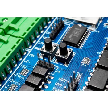
Hardware Assembly
Before soldering you should clear about the Power and Control Signal. Do not mix up between them. Otherwise, you will fry everything.
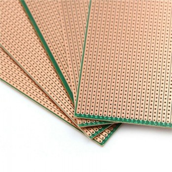
To assemble all the components as per the circuit diagram I used the Zero PCB or a Vero Board.

For our project, I used 24V Solar Panel. The Solar Panel is huge and can collect a large quantity of light. The Solar Panel is connected at the Input Terminal of the assembled circuit. Similarly a 12V, 7Ah Lead-Acid Battery is connected as a battery Terminal. The Load can output the required voltage. The Load can be directly connected to an Inverter or some battery-operated devices.

To power the Arduino Nano Board and some other part of the circuit, a 5V-9V DC Adapter can be used.
It doesn't stop here there is more about programming, final display & Video Tutorial & Guide of the project on PART 2...

Comment