


22 Mar

0 Comment(s)
1585 View(s)
Hey, what's up, Guys!
Today, we are going to go through A9G GPS, GSM, and GPRS module from AI Thinker. There are several other modules as well such as A9 and A6 from AI Thinker which have similar GSM and GPRS capabilities but the special thing about A9G is that with GSM and GPRS capabilities it is GPS enabled as well and is capable in doing GPS related functions which gives it an edge over other modules.
In this tutorial, we will try the functioning of the GPS capabilities of this module and after that, towards the end, we will also check the functioning of the module in GSM and GPRS mode.
So Let's jump straight into it...
Step 1: About A9G Module.


The A9G is a complete quad-band GSM / GPRS module that combines GPRS and GPS / BDS technologies and integrates it in a compact SMD package, saving customers time and money in developing GNSS applications.
The A9G by default comes with a bootloader or firmware and hence it can be controlled using AT commands through Arduino, ESP8266, and Raspberry Pi as well. It can be used to connect modules such as Arduino and Raspberry Pi to the internet and can be used in a wide range of IoT applications and is ideal for IoT applications for home automation, industrial wireless control, wearable electronics, wireless location sensing devices, wireless location system signals and other IoT applications.
A9G SMD package uses the standard SMT equipment to achieve the rapid production of products, especially for automation, large-scale, low-cost modern production methods for the convenience of a variety of Internet of Things hardware terminal applications.
For detailed reading about the functioning and the features of the module, you can refer to this link.
Step 2: Features and Pinout of A9G Module


Some Important Features of the module are:-
1) Complete quad-band GSM / GPRS module, 800/900/ 1800 / 1900MHz
2) SMD package for easy MP & testing
3) Low power mode, average current 2mA or less
4) Supports GPS, BDS.
5) Supports digital audio and analog audio, supports HR, FR, EFR, AMR voice coding
6) Support voice calls and SMS messages
7) Embedded network service protocol stack
8) Support standard GSM07.07,07.05AT command and Anxin expandable command set
9) Support PBCCH - Supports firmware upgrade via serial port.
The Pin diagram for this module is as shown in the image above. The Technical specifications of this module can be referred from here.
Structural details of the module are as mentioned below:-
1) 1 A9G module
2) 29 GPIOs with 2.45mm spacing (with 2 download debug pins (HST_TX, HST_RX)
3) One SIM card slot (Nano Card < Micro Card < Standard Card)
4) 1 TF card slot
5) 1 GPRS interface with IPEX
6) 1 generation package
7) 1 GPS interface with IPEX
8) 1 generation package
9) 1 micro USB interface5v-4.2V DC-DC, it can be 5v power supply or 3.8 ~ 4.2V power supply
10) 1 power key, a reset button,2 LED,1 microphone.
Step 3: AT Commands Useful for GPS and GPRS Functioning.
As the A9G module comes with an inbuilt bootloader and hence it can be controlled using AT commands and can also be used to transmit commands as well. Some useful AT commands are:-
- AT+GPS=1: This command is used to enable GPS. When this command is sent the GPS is turned On and the LED on module for GPS starts blinking.
- AT+GPS=0: This command is used to turn OFF GPS. After sending this command GPS is turned OFF and LED also stops blinking
- AT+GPSRD=1: This command is used to start reading GPS data and display it on the monitor. The data returned by this command is in NMEA format which needs to be converted to get into a readable form.
- AT+GPSRD=0: This command is used to stop reading the GPS data.
- AT+LOCATION=1: This command is used to get location data through the LBS server. It displays the location information in the form of latitude and longitude.
- AT+GPSUPGRADE: Release GPS UART from A9’s CPU, then you can connect GPS UART directly to communicate with GPS.
- AT+CGPSPWR: This command is used for GPS Power Control. It is used to turn on or turn off the GPS Power supply
- AT+CGPSRST: This command resets GPS in COLD start mode or autonomy mode.
- AT+CGPSRST=0 resets GPS in cold start mode and command
- AT+CGPSRST=1 resets GPS in autonomy mode.
- AT+CREG?: This command is used to check whether we are registered to the network or not. If it shows 1,1 as a response then this means that we are registered and can move ahead.
- AT+CGATT: This command is similar to the CREG command. If its response is 1 then we are connected to the network.
- AT+CIPSTATUS: This command is used to check whether the IP is connected or Not. If its response is "INITIAL" then it means that we are connected. If it shows something else then there is some problem.
- AT+CGDCONT=1: This command is used to connect to the Internet. In this command, we need to specify the APN and IP as well in the format given as AT+CGDCONT=1, "IP", "www"
- AT+HTTPGET: This command is used to send an HTTP get request to any server link. Its format is AT+HTTPGET="server link".
- AT+CIPMODE: This is used for selecting TCP/IP application mode. '0' os non-transparent mode and '1' is the transparent mode.
- AT+CIPACK: This command checks the state of data transmission. It will return the amount of data sent, data acknowledged by the server, and data not confirmed by the server.
Step 4: Using GPS and GPRS Functions of A9G Module


Here we are going to use the GPS and GPRS functions of the A9G module. We will be using AT commands to control the module and do different tasks. As this module operates on 5V we will use a USB to Serial converter to supply it the 5V supply.
Steps for Connecting module to PC:-
1) Connect the GSM and GPS antennas to the A9G module.2) Insert a SIM card in the SIM card slot and a Micro SD card in the SD card slot
3) Connect the Vcc and GND Pin of the module to the Vcc and GND of the USB to Serial Converter.
4) Connect the Rx Pin of the A9G to the Tx pin of the Converter and Tx Pin of A9G to the Rx pin of the converter and connect it to your PC.
5) Open AI Thinker Tool and select the correct COM port and baud rate(In this case it is 115200) and click open Serial button.
Steps for using GPS functions of the module:-
1) In the command, section write command AT and click Send button. It must display OK on the monitor which shows that your module is connected successfully.2) Now to enable GPS we need to send a command AT+GPS=1. This turns ON the GPS and as it turns ON the GPS LED starts blinking.
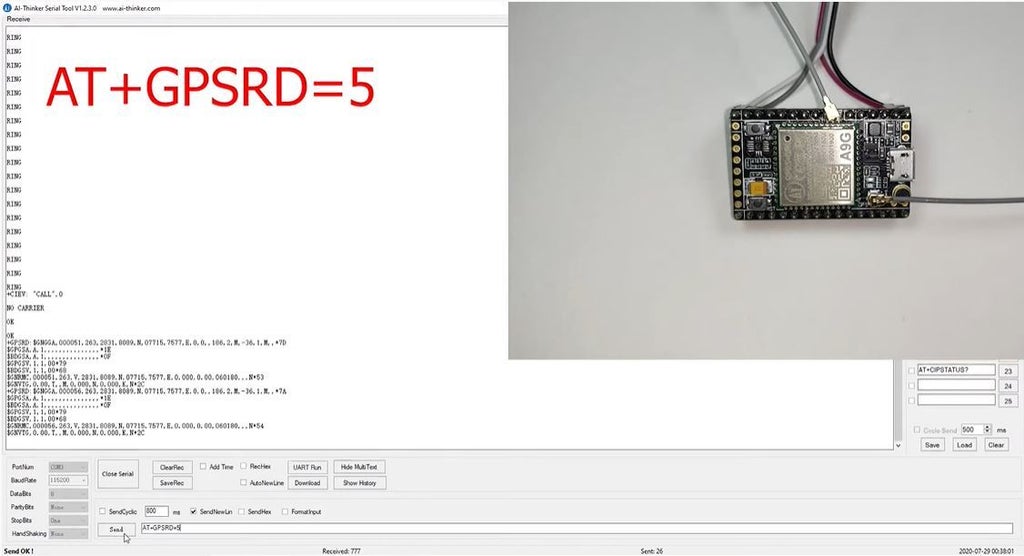
3) After this, we will send a command AT+GPSRD=5. This command will read the GPS data and send it to the monitor after every 5 seconds. The Data appearing on the Monitor would be in NMEA format which can be converted to get the GPS data details.
4) To stop this we need to send command AT+GPSRD=0 and it will stop sending GPS data and after that send the command AT+GPS=0 which will disable GPS as well.
Steps for using GPRS functions of the module:-
1) To check the status of the GPRS we can use commands such as AT+CREG? if this command shows 1,1 on the monitor it means that we are registered to the network. Similarly, we can use AT+CGATT command which shows 1 when we are connected to the network;2) To connect to the Internet using GPRS we need to send a command which is AT+CGDCONT=1, "IP", "www". where "IP" is the Internet Protocol and "www" is the Access Point Name which can be different in your case. As we send the command it should display OK which means that we are connected to GPRS.
3) Use AT+CIPSTATUS command to check whether IP is connected or not it should display "Initial".
4) To send an HTTP request we need to type a command which is AT+HTTPGET="any server link" this will send a get request to the server link which is mentioned after the "=" sign. As the command is sent, the monitor will display the data received and in that the bottom line is the response sent by the server.
Step 5: Using GSM Functionality of A9G Module

The A9G module has GSM capabilities with the help of which it can be used to start a call, receive a call, and send an SMS as well when we dial the number whose SIM card is inserted within the A9G module a "RING" message will continuously appear on the monitor. The AT Commands which can be used for calling and sending SMS using the A9G are:-
Call Commands:-
- ATA: Used to Answer an Incoming Call. On sending this command "+CIEV: "CALL",1 CONNECT"; the message is received.
- ATD: This Command is used to dial a number this command is sent as "AT+number to be dialed" and on sending this command we receive a message saying "ATD+number dialed OK +CIEV: "CALL",1 +CIEV: "SOUNDER",1 ";
- ATH: This command is used to disconnect a call. This command is sent as "ATH" and on sending this we receive a message "+CIEV: "CALL",0 OK";
- AT+SNFS=0: This command used to enable any earphones/headphones connected to the module. This command enables them.
- AT+SNFS=1: This command is used to enable Loudspeaker selection.
- AT+CHUP: This command causes the mobile terminal to hang up the current call
- AT+CMGF=1: This command is used to select the SMS message format. On sending his command we receive an OK. This is to read and write SMS messages as strings instead of hexadecimal characters.
- AT+CMGS: This command is used to send SMS to a given mobile number. The format for sending this command is "AT+CMGS=” mobile number”.On sending this command the monitor will show > You can now type the message text and send the message using the - key combination: TEST After some seconds the modem will respond with the message ID of the message, indicating that the message was sent correctly: "+CMGS: 62". The message will arrive on the mobile phone shortly.
- AT+CMGL: This command is used to read SMS messages from preferred storage.
Step 6: That's It!
So this was it from the tutorial as you can see that the A9G module is capable of doing many things such as GPS functions, GPRS functions such as calling, sending SMS, connecting to the internet, etc which makes it very useful in IoT related applications where we need to use GPS location data as well. As it can be driven using AT commands it is very easy to operate this module and can prove to be a good and compact tool for your projects.Get started your project by visiting our online shop

Comment