





















- Stock: Out Of Stock
- Model: Keypad 4X3
- Weight: 22.00g
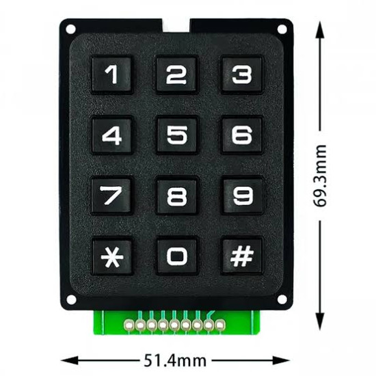
- Dimensions: 70.00mm x 52.00mm x 12.00mm
- SKU: 116
Architectural Overview and Matrix Topology Design
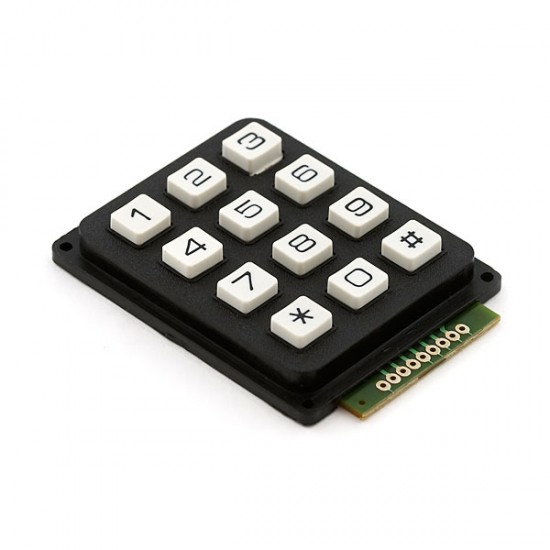
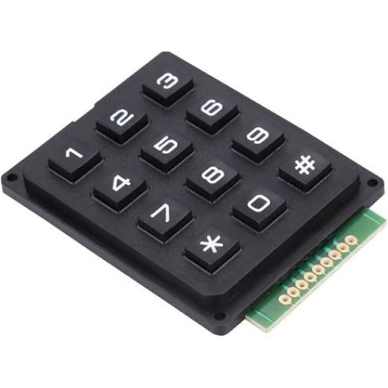
The 12-button matrix keypad is an essential human-machine interface component engineered for seamless digital input in embedded systems, microcontrollers, and electronic prototype development. Utilizing a standardized 3x4 layout featuring digits 0 through 9 along with standard telephone keypad symbols Asterisk and Hash, this input device minimizes microcontroller resource usage through a multiplexed matrix topology. Rather than requiring 12 dedicated general-purpose input/output pins for individual tactile switches, this peripheral arranges the switches into 4 rows and 3 columns, driving user interactions through only 7 signal pins. This design reduces I/O pin consumption by more than 41 percent, preserving vital microcontroller digital lines for sensors, displays, communication buses, and actuator driver circuits.
Each button in the matrix represents a normally-open momentary tactile switch situated at the intersection of a specific row and column line. When a user depresses a key, it creates a momentary electrical short circuit between the corresponding row trace and column trace. Microcontrollers evaluate keypresses by executing a continuous matrix scanning routine, sequentially driving output pins LOW or HIGH and sampling the input pins to detect current paths. Built on a durable composite substrate with high-tactility dome switches or rubber conductive pads, this module ensures reliable physical feedback, low contact resistance, and long service life across demanding human-interface applications.
Technical Specifications and Electrical Parameters
Understanding the electrical tolerances and physical parameters of the matrix keypad is critical for integrating it safely into high-reliability hardware architectures. Below are the core parameters governing the performance of this keypad:
Maximum Operating Voltage: 24V DC. Maximum Operating Current: 30mA DC. Contact Resistance: Initial contact resistance is less than 100 Ohms, rising to a maximum of 200 Ohms over the product operational lifetime. Insulation Resistance: Greater than 100M Ohms at 100V DC. Dielectric Withstand Voltage: 250V RMS at 50/60Hz for a duration of one minute without breakdown or arc-over. Mechanical Actuation Force: 180 grams to 250 grams, providing clear tactile snap response. Key Travel Distance: 0.5mm to 1.5mm depending on tactile enclosure geometry. Bounce Time: Less than 5 milliseconds during contact make and break cycles. Operating Temperature Range: -20 degrees Celsius to +60 degrees Celsius. Storage Temperature Range: -40 degrees Celsius to +85 degrees Celsius. Key Lifetime Expectancy: Standard mechanical rating exceeds 1,000,000 actuations per individual key position.
Pinout Architecture and Hardware Signal Mapping
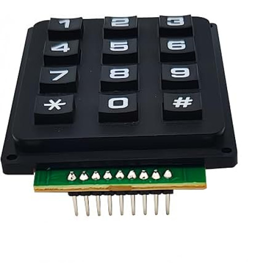
The 12-button matrix keypad features a standard 0.1-inch (2.54mm) pitch single-row male header interface designed for directly mating with breadboards, female jumper cables, or custom printed circuit board sockets. The 7 output pins correspond directly to the matrix grid layout. Understanding this mapping is essential for configuring input pull-up resistors and driving output logic in software drivers.
Pin 1 (Row 1 Signal Line): Connects internally to the top terminal of key buttons 1, 2, and 3. In standard scanning code, this line is assigned as an I/O pin capable of tri-state output or input with internal pull-up.
Pin 2 (Row 2 Signal Line): Connects internally to the top terminal of key buttons 4, 5, and 6. Serves as the second scanning line in the row vector configuration.
Pin 3 (Row 3 Signal Line): Connects internally to the top terminal of key buttons 7, 8, and 9. Controls the third horizontal array segment of the input matrix.
Pin 4 (Row 4 Signal Line): Connects internally to the top terminal of key buttons Asterisk, 0, and Hash. Represents the bottom horizontal line of the keypad array.
Pin 5 (Column 1 Signal Line): Connects internally to the bottom terminal of key buttons 1, 4, 7, and Asterisk. Acts as the leftmost vertical detection rail in matrix scanning routines.
Pin 6 (Column 2 Signal Line): Connects internally to the bottom terminal of key buttons 2, 5, 8, and 0. Acts as the central vertical detection rail for the middle key column.
Pin 7 (Column 3 Signal Line): Connects internally to the bottom terminal of key buttons 3, 6, 9, and Hash. Acts as the rightmost vertical detection rail in the keypad matrix.
Microcontroller Multiplex Scanning and Software Logic
Operating the matrix keypad relies on active dynamic scanning executed by an embedded microcontroller such as an AVR, ARM Cortex-M, PIC, ESP32, or STM32 architecture. The standard scanning technique involves setting the 4 Row pins as digital outputs and the 3 Column pins as digital inputs configured with internal software pull-up resistors enabled (or external physical 10k Ohm pull-up resistors connected to VCC).
Under idle conditions, all Row output pins are held at logic HIGH level (3.3V or 5V depending on system voltage). Because internal pull-ups keep Column input pins pulled HIGH, reading the Column pins yields a logic state of HIGH across all three columns. When a matrix scan cycle initiates, the firmware pulls Row 1 LOW while keeping Rows 2, 3, and 4 in a high-impedance state or HIGH logic level. The firmware immediately reads the logic levels of Columns 1, 2, and 3. If Key 2 is pressed, Column 2 becomes electrically pulled LOW through the closed contact switch to Row 1. The software cross-references the active LOW Row (Row 1) and active LOW Column (Column 2) to identify Key 2 as the active button.
The scan routine sequentially iterates through Rows 2, 3, and 4 at high frequencies (typically 100Hz to 1kHz scanning frequency). Because the entire scan sequence completes in a fraction of a millisecond, human users perceive button detection as instantaneous response.
Switch Contact Debouncing and Multi-Key Rollover Mitigation
Mechanical switches suffer from contact bounce, a phenomenon where metallic contacts physically bounce off one another for several milliseconds when pressed or released before settling into a stable closed or open electrical connection. Left unhandled, a single keypress produces rapidly alternating HIGH and LOW logic states that microcontrollers misinterpret as multiple rapid key presses.
Debouncing can be solved in hardware using an RC low-pass filter (a 10k Ohm resistor paired with a 100nF ceramic capacitor across the column line feeding into a Schmitt Trigger input stage) or in software using state-machine timing logic. Software debouncing tracks key state transitions and requires a key state to remain completely stable for 10 to 20 consecutive milliseconds before registering a valid press event.
In matrix keypad topologies, pressing three or more keys simultaneously can induce a condition known as ghosting, where an unpressed button appears closed due to alternate current paths formed through adjacent closed switches. To prevent ghosting and enable multi-key rollover capabilities in high-security applications, hardware designers can install small signal diodes, such as 1N4148 switching diodes, in series with each matrix switch node to force unidirectional current flow.
Detailed Application Use-Cases
1. Digital Security Access Control Keypad: Integrated into electronic door locks, safes, and secure building entry systems. The keypad receives user PIN codes and passes the sequence to an embedded security processor. When combined with non-volatile EEPROM memory, administrators can set, reset, and validate multi-digit security passcodes locally without requiring network connectivity.
2. Industrial Automation System Parameter Input: Used on manufacturing machinery control panels to allow machine operators to input numerical processing variables, cycle counts, temperature setpoints, and operational delay durations. Its rugged mechanical construction makes it resilient against ambient electromagnetic noise in factory environments.
3. Custom MIDI Synthesizer and Audio Controller: Synthesizer builders utilize matrix keypads as numeric pitch select controls, preset patch selectors, or step-sequencing input panels. Coupled with an Arduino or Teensy board processing MIDI commands, users can switch sound banks, alter delay timing, or trigger musical sequences on the fly.
4. Smart Home Automated Lock Mechanism: Installed on exterior gates or residential smart locks linked to Home Assistant or custom ESP8266 or ESP32 microcontrollers. Users enter authentication sequences that trigger relay modules, solenoids, or servo motors to unlock deadbolts while logging access timestamps to remote databases.
5. Point of Sale (POS) Terminal Emulator: Software and hardware engineering teams build POS hardware testing fixtures using matrix keypads to simulate pin-pad credit card processing equipment, cash register data entries, and inventory tracking inputs during system development and testing.
6. Long-Range RF Telemetry Remote Transmitter: Embedded into handheld wireless transmitters operating on Lora, NRF24L01, or 433MHz frequencies. Field operators select specific drone commands, telemetry queries, or remote relay triggers by typing short numeric command codes sent over wireless radio frequencies.
7. Educational Microcontroller Experimentation Board: Found extensively in STEM electronics labs, university engineering courses, and maker trainer kits. Teaching matrix scanning algorithms provides students with real-world foundation in multiplexing techniques, state machines, interrupt handlers, and input debouncing algorithms.
8. Flight Simulator Cockpit Radio Panel: Flight simulator enthusiasts build realistic replica cockpit assemblies using matrix keypads to control avionics stacks, VHF radio frequencies, transponder Squawk code entries, and autopilot altitude or heading values within Microsoft Flight Simulator or X-Plane environments.