





















- Stock: In Stock
- Model: JST XH2.54 XH 2.54 2-Pin Connector Set
- SKU: 1455
Product Overview and Engineering Design
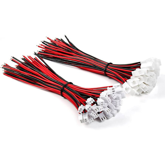
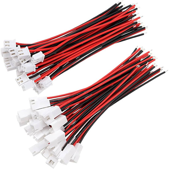
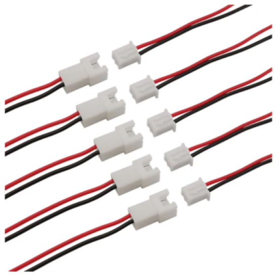
The JST XH 2.54mm pitch 2-pin connector set represents an industry-standard interconnect solution engineered specifically for high-reliability, low-profile electrical connections across modern electronics, robotics, and radio-controlled hobby systems. Designed around the established Japan Solderless Terminals XH design architecture, this connector assembly provides a seamless balance between compact mechanical dimensions and robust electrical performance. The set includes a pre-crimped female wire harness integrated with 150mm of 24AWG stranded copper hookup wire, alongside a matching 2-pin male straight header designed for standard through-hole printed circuit board assembly. This complete pair provides hardware designers, embedded system engineers, and system integrators with an end-to-end interface solution for sub-assembly power routing, sensor integration, and modular subsystem interconnections.
Comprehensive Electrical Performance Parameters
Engineered to operate reliably under demanding ambient and operational conditions, the JST XH 2-pin system supports a maximum current rating of 3.0 Amperes AC or DC per contact when paired with the included 24AWG conductor. Operating at a maximum rated voltage of 250V AC/DC, the contact retention structure and insulating material exhibit exceptional dielectric integrity. The dielectric withstand voltage rating is tested up to 1000V AC for a duration of one minute without insulation breakdown or flashover. Initial contact resistance is maintained below 20 milliohms, ensuring minimal voltage drop across the interface even during peak current draw. Furthermore, the high-performance Nylon 66 housing material provides a minimum insulation resistance of 1000 Megohms measured at 500V DC, preventing cross-channel leakage current and maintaining electrical isolation between adjacent pins across an operating temperature range of -25 degrees Celsius to +85 degrees Celsius.
Mechanical Construction and Material Integrity
The mechanical longevity and operational dependability of this JST XH set stem from high-grade raw materials and precise manufacturing tolerances. The female connector housing and male PCB header base are molded from high-density Nylon 66, rated UL94V-0 for flame retardancy and thermal stability. The internal female socket contacts and male header pins are formed from high-conductivity phosphor bronze alloy, treated with a electro-plated tin finish over a nickel underplate. This multi-layer plating prevents surface copper oxidation, reduces mating friction, and maintains stable contact pressure over a minimum mechanical life of 50 mating cycles. The included 150mm red and black conductors feature high-strand count annealed copper wire insulated with flexible, flame-resistant PVC. The wire crimp terminals are cold-welded onto the 24AWG wire strands using precision automated crimp dies, ensuring a gas-tight gas-proof connection that resists vibration fatigue and mechanical tension.
Polarization and Friction-Locking Mechanics
Mis-mating or reverse polarity connections can instantly destroy sensitive microcontroller units, logic circuits, and power regulators. To eliminate human error during assembly and field maintenance, the JST XH housing incorporates physical keying guides along the lateral sides of the female connector body. These keys slide into matching keyway channels on the male PCB header shroud, making reverse insertion physically impossible without applying excessive destructive force. Additionally, the housing system incorporates a subtle positive friction-lock mechanism. As the female wire harness is inserted into the male PCB header, elevated ramp tabs on the header engage corresponding recesses on the female plug body. This friction lock provides tactile feedback upon full insertion and prevents unintentional dislodgement caused by high-vibration operational environments, such as motorized robotic platforms and RC aircraft chassis.
Structural Pinout and Configuration Details
The JST XH 2-pin connector set follows a standardized 2.54mm (0.100 inch) center-to-center pin spacing, aligning perfectly with standard prototyping breadboards, matrix boards, and conventional 0.1 inch grid PCB hole layouts. The pinout structure is defined logically by the standard red and black color-coded wire harness:
Pin 1 (Red Wire): Positive Voltage Supply (VCC / V+ / Positive Battery Terminal). Assigned to carry DC positive supply voltage or high-side signal lines.
Pin 2 (Black Wire): Common Ground Return (GND / V- / Negative Battery Terminal). Assigned to establish common system ground reference or low-side signal return paths.
When viewed facing the front mating face of the male PCB header with the locking guide notch oriented upward, Pin 1 is conventionally located on the left-hand side, while Pin 2 occupies the right-hand position. This consistent mechanical orientation simplifies wire routing layout diagrams and reduces wiring assembly times during production runs.
Technical Application Use-Cases
1. LiPo and NiMH Battery Pack Interfaces: Widely utilized in single-cell (1S) and dual-cell (2S) lithium polymer or nickel-metal hydride battery assemblies for small RC vehicles, drones, and handheld test equipment. The connector functions either as a low-current main power plug or as a balance charger tap interface for cell monitoring.
2. Robotic Sensor Modules: Serves as an ideal quick-disconnect interface for ultrasonic distance sensors, infrared proximity modules, optical encoders, and limit switches mounted on mobile robotic chassis, enabling modular replacement without soldering directly to main controller boards.
3. 3D Printer Subsystem Wiring: Commonly deployed on popular 3D printer controller boards (such as RAMPS, SKR, and Creality mainboards) to connect mechanical endstop switches, thermistor temperature sensors, hotend cooling fans, and part-cooling blower units.
4. Microcontroller Power Input: Acts as a reliable dedicated power input port for development boards like Arduino, ESP32, and Raspberry Pi carrier cards, allowing external power supplies or battery enclosures to be detached cleanly during firmware flashing or hardware upgrades.
5. RC Model Receiver and Lighting Auxiliary Controls: Provides direct pluggable connections for auxiliary LED lighting systems, telemetry modules, sound simulators, and micro servos operating within remote-controlled cars, boats, and fixed-wing aircraft.
6. Custom IoT Edge Node Enclosures: Utilized in compact internet of things field nodes to bridge internal battery charging circuits with external solar harvesting panels or localized battery cells housed within weatherproof IP-rated enclosures.
7. Consumer Audio and Speaker Assembly: Used internally within portable Bluetooth speakers, desk radios, and intercom devices to connect full-range dynamic speaker drivers and internal microphone modules to the main audio amplifier printed circuit board.
8. DIY Quadcopter LED Status and Buzzer Indicator Wiring: Installed on multirotor racing drones to supply power to high-intensity tail LEDs and audible low-voltage alarm buzzers connected directly to flight controller auxiliary pad headers.
PCB Layout and Soldering Integration Guidelines
When integrating the male JST XH 2-pin header into custom printed circuit board designs, designers should specify a through-hole pad layout with a center-to-center hole pitch of precisely 2.54mm. Recommended PCB drill hole diameter for the square profile terminal pins is 0.95mm to 1.05mm, with an outer pad diameter of 1.6mm to ensure optimal solder filleting. The header pins are constructed from tin-plated copper alloy suited for both manual hand-soldering and automated wave soldering processes. For manual soldering, maintain iron tip temperatures between 340 degrees Celsius and 360 degrees Celsius with a contact dwell time of under 3 seconds per pin to avoid thermal deformation of the surrounding Nylon 66 plastic shroud. Clean rosin or no-clean flux residues using isopropyl alcohol to ensure long-term insulation resistance between the adjacent 2.54mm pitch trace pads.