Menu
Your Cart

Arduino Uno R3 Microcontroller Board

Arduino Uno R3 Microcontroller Board
USB CABLE INCLUDED Special Offer Top Seller
Arduino Uno R3 Microcontroller Board
KES 1,500.00
  • Stock: In Stock
  • Model: Arduino Uno R3 Microcontroller
  • Weight: 25.00g
  • Dimensions: 68.60mm x 53.40mm x 15.00mm
  • SKU: 1

Product Overview

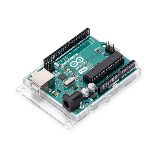
The Arduino Uno R3 stands as the definitive reference platform for physical computing and embedded system design. Driven by the high-performance, low-power AVR 8-bit ATmega328P microcontroller, this platform bridges the gap between complex hardware engineering and accessible software development. Designed for hardware prototyping, academic research, industrial control, and custom robotics, the Uno R3 offers a stable, standard form factor integrated with reliable power circuitry and expanded peripheral interfacing.

MicrocontrollerATmega328P
Operating Voltage5V
Input Voltage (recommended)7-12V
Input Voltage (limit)6-20V
Digital I/O Pins14 (of which 6 provide PWM output)
PWM Digital I/O Pins6
Analog Input Pins6
DC Current per I/O Pin20 mA
DC Current for 3.3V Pin50 mA
Flash Memory32 KB (ATmega328P) of which 0.5 KB used by bootloader
SRAM2 KB (ATmega328P)
EEPROM1 KB (ATmega328P)
Clock Speed16 MHz
LED_BUILTIN13
Length68.6 mm
Width53.4 mm
Weight25 g

Microcontroller Architecture and Performance

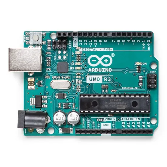
At the core of the Uno R3 is the Microchip ATmega328P running at a precise 16 MHz clock rate via an onboard ceramic resonator. The architecture features 32 KB of in-system programmable flash memory (with 0.5 KB reserved for the optiboot bootloader), 2 KB of SRAM for dynamic state memory, and 1 KB of EEPROM for non-volatile parameter storage. Unlike legacy microcontroller boards, the Uno R3 utilizes a dedicated ATmega16U2 microcontroller programmed as a USB-to-serial converter instead of an external FTDI driver chip. This configuration delivers faster data transfer rates, driverless deployment across modern operating systems, and the ability to reprogram the USB controller as a native USB human interface device (HID) like a keyboard or MIDI instrument.

Input Output Capability and Peripheral Mapping

The board breaks out 14 digital input and output pins along with 6 dedicated analog inputs. Each digital pin operates at 5V logic with a recommended maximum current sourcing or sinking capability of 20 mA (40 mA absolute maximum DC limit). Six of these digital channels (Pins 3, 5, 6, 9, 10, and 11) feature hardware-based 8-bit Pulse Width Modulation (PWM) outputs suitable for precision DC motor control, servo drive signals, and variable LED illumination. The 6 analog input channels (A0 to A5) feed an integrated 10-bit successive-approximation analog-to-digital converter (ADC), providing 1024 discrete voltage resolution levels between ground and a 5V reference. High-speed serial bus systems are supported through hardware UART on Pins 0 (RX) and 1 (TX), SPI protocol via dedicated headers or Pins 10 (SS), 11 (MOSI), 12 (MISO), and 13 (SCK), and I2C/TWI communication exposed through dedicated SDA and SCL headers near the AREF pin.

Power Dynamics and Board Level Protection

Power management on the Uno R3 is designed for versatile field deployment and automated safety. The system supports power delivery through either the USB Type-B port or an external DC power supply connected via the 2.1mm center-positive barrel jack or the VIN header pin. An integrated auto-voltage selection circuit dynamically switches between USB power and external power without interrupting operation when an external source between 7V and 12V DC is detected (operating limits range from 6V to 20V). Onboard low-dropout (LDO) linear regulators deliver clean 5V and 3.3V power rails for external sensors and auxiliary modules. A resettable polyfuse protects the connected host computer USB port from overcurrent or short-circuit faults by tripping if current exceeds 500 mA.

Ecosystem Compatibility and Prototyping Uses

The R3 revision introduces the modernized standard pinout configuration, adding the IOREF pin to allow connected hardware shields to adapt seamlessly to the host board logic level, alongside a non-connected (NC) pin reserved for future expansion. The physical footprint matches all standard official shields, allowing instant hardware modularity for Ethernet communication, motor driving, wireless networking, and data logging. Typical application domains range from educational STEM kits and automated test fixtures to environmental sensing arrays, IoT edge nodes, and custom mechatronics control setups.

Official Resources & Manuals

Ginō Ginō AI - Nerokas AI Assistant
Jambo! I am Ginō, a Nerokas AI Assistant and Africa's best Open Hardware Facilitator AI agent here to help. In order to serve you better and to help me give you accurate shipping estimates as we begin, could you please tell me your name and your location/city?

You can also ask about any hardware or type I'd like to order, I am looking for..., you can also LIST all SKUs & Quantity of desired items from our website here for me to help you Checkout automatically at anytime to fast-track your requests and orders.