Out Of Stock


Digital Voltmeter Ammeter Dual Display 10A, 0-100VDC
KES 500.00
- Stock: Out Of Stock
- Model: Digital Voltmeter Ammeter Dual Display
- SKU: 2662
Your shopping cart is empty!


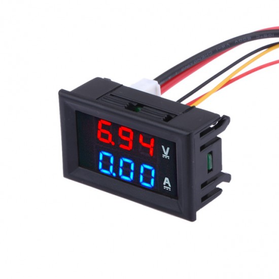
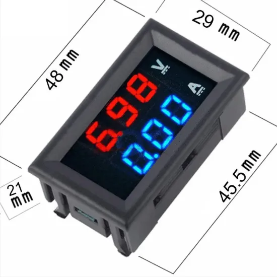
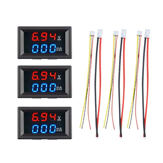
The Dual Display LED Digital Voltmeter Ammeter Module is an essential instrumentation component designed for real-time electrical telemetry in custom electronic projects, industrial monitoring control panels, automotive applications, and power supply diagnostics. Featuring a compact form factor measuring 48mm by 29mm with a depth of 21mm, this panel-mount gauge integrates two independent 0.28-inch three-digit seven-segment LED displays. The top display illuminates in high-contrast red to provide instantaneous DC voltage monitoring from 0.0V up to 100V DC, while the bottom display illuminates in vivid blue to track DC current draws up to 10.0A direct through an onboard precision shunt resistor. Engineered for rapid integration, this panel meter requires a minimal mounting cutout of 45.5mm by 26.5mm, snapping firmly into standard enclosure faceplates using built-in side retention clips.
At the core of this telemetry module is an optimized 8-bit microcontroller coupled with high-speed analog-to-digital converters (ADCs) designed to continuously sample both potential difference and current flux across low-side sense nodes. Operating off an auxiliary input power supply range of DC 4.5V to 30V, the internal electronics consume fewer than 20mA during full display illumination. The unit maintains an operational voltage sampling range of 0V to 100V DC with a minimum resolution of 0.1V and a measurement accuracy rating of plus or minus 1 percent, offset by plus or minus 1 count digit. Current measurement spans 0.00A to 10.0A with a fine resolution of 0.01A (10mA). Sampling and visual output updating occur at a refresh rate equal to or greater than 500 milliseconds per cycle, striking a stable balance between telemetry responsiveness and human-readable digit flicker suppression. The hardware is thermal-rated to perform reliably within ambient environments ranging from -10 degrees Celsius to +65 degrees Celsius under non-condensing relative humidity conditions between 10 percent and 80 percent.
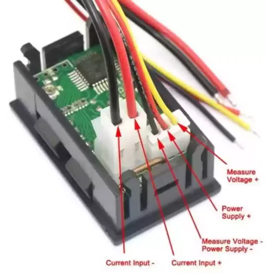
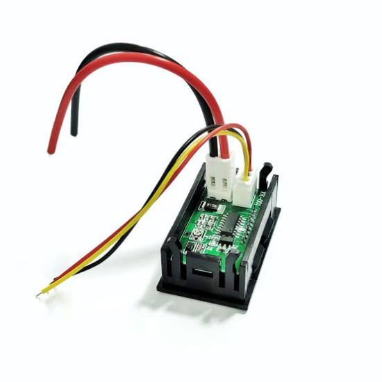
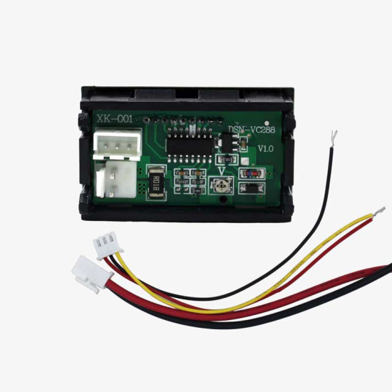
The meter features two separate connector blocks on its rear PCB: a thin three-wire harness dedicated to system power and high-impedance voltage sensing, and a thick two-wire harness designed for low-impedance high-current measurement pathing. Proper wiring geometry must be strictly observed to prevent catastrophic ground loop damage or inaccurate readings caused by common-mode offset voltage shifts.
1. Thin Red Wire (Operating Power Supply Positive - VCC): Connects to an auxiliary or source DC voltage source between 4.5V and 30V maximum. This pin provides current to power the microcontroller and the dual LED numeric arrays. Exceeding 30V DC on this wire will destroy the internal linear regulator circuit.
2. Thin Black Wire (Operating Power Supply Negative / Signal Ground - GND): Serves as the logic ground reference for the internal electronics. When powering the meter from the exact same load source being measured (provided the source is between 4.5V and 30V), this thin black wire is internally common-grounded to the thick black current wire. If an isolated auxiliary supply is used, this connects to the auxiliary supply negative line.
3. Thin Yellow (or White) Wire (Voltage Sensing Input - VIN): Connects directly to the positive potential node of the circuit or load under test. This high-impedance input taps into an internal voltage divider network, allowing continuous measurement of DC potential from 0.0V up to 100V relative to the system common ground.
4. Thick Red Wire (Current Load Return Input - I+): Connects directly to the negative terminal of the load being monitored. Current flowing out of the electrical load enters the meter through this thick gauge wire, passes through the low-resistance internal manganese-copper alloy shunt resistor, and exits back to the power supply negative output. Never connect this thick red wire directly to a positive voltage source.
5. Thick Black Wire (System Power Supply Negative Return - I-): Connects directly to the negative terminal of the main DC power source or battery. This wire completes the high-current return path from the internal shunt resistor back to the supply origin. Because the ammeter utilizes a low-side sensing topography, it must always sit between the load negative output and the main power supply ground.
To measure direct currents up to 10 amperes without requiring an external shunt block, this digital meter integrates a precision low-side shunt resistor directly on its printed circuit board assembly. Constructed from a low Temperature Coefficient of Resistance alloy, the shunt generates a tiny millivolt drop proportional to the total current flowing through the thick wire harness according to Ohm's Law. The onboard microcontroller differential ADC converts this millivolt potential into a digitally scaled current value displayed on the blue 0.28-inch LED digits. Because the internal trace geometries and wire gauges are engineered specifically for up to 10A continuous loads, external shunts are completely unnecessary. However, note that attempting to measure continuous loads under 1A may result in reduced accuracy due to lower dynamic range resolution on low-end signal-to-noise thresholds.
The module operates on a shared ground plane where the thin black signal wire and thick black current wire are bonded internally on the circuit board. When designing circuits using this device, engineers must recognize that low-side current sensing disrupts a pure zero-ohm path between the load ground and power supply ground by inserting the tiny milliohm resistance of the internal shunt. Therefore, all current leaving the system load must route through the thick red wire, pass through the internal shunt, and exit via the thick black wire. Introducing secondary parallel ground paths around the module will bypass the shunt resistor, resulting in artificially low or zero current readings on the blue LED display.
In custom-built or retrofitted DIY benchtop power supplies, this module functions as an real-time feedback panel. By wiring the thin yellow wire to the variable output positive rail, the thin red wire to a fixed internal auxiliary rail (such as a 12V or 5V bias supply), and running the load return through the thick red and black wire pair, users gain instantaneous dual visual feedback on voltage regulation and current draw across experimental loads.
For small-scale photovoltaic systems, this meter offers a complete telemetry panel when positioned between a solar charge controller and a low-voltage battery bank or load array. Installers can track variable solar array terminal voltages up to 100V on the red LED display, while monitoring charge currents entering the battery up to 10A on the blue display, allowing for fast verification of panel yield and load efficiency.
Overland vehicles, RVs, and marine vessels equipped with dual battery systems rely on accurate voltage tracking to prevent deep discharge of starter batteries. This meter can be mounted on dashboard switch panels to display the secondary auxiliary battery bank's voltage (0-30V nominal range) while concurrently tracking current draw from accessory circuits, refrigerators, or lighting arrays connected through the low-side thick wiring harness.
In lightweight electric mobility platforms such as 24V, 36V, 48V, or 72V custom golf carts, e-bikes, and utility scooters, monitoring system traction battery state of charge is vital. Capable of handling up to 100V DC input, the voltage sensing wire monitors the total pack voltage drop under acceleration, while the ammeter path monitors continuous drive motor current draw up to 10A, providing immediate insight into motor load, efficiency, and peak draw limits.
Battery pack builders and reconditioners can integrate this digital panel meter into automated or manual constant-current discharge test benches. During cell capacity tests, the voltage channel tracks cell or module voltage degradation curves over time down to 0.1V resolution, while the current channel verifies that the constant-current sink load remains steadily pulled within the desired discharge parameters.
Electronics repair facilities and manufacturing lines require burn-in load stations to stress-test DC-DC converters and AC-DC switch-mode power supplies. Mounting this module into a load testing fixture allows quality assurance technicians to visually verify power supply cross-regulation under changing resistive load conditions, catching voltage droop and current overload trip points instantly.


High-power LED arrays require precise forward voltage and current management to prevent thermal runaway. When dialing in buck or boost LED drivers, this meter provides dual-parameter oversight. Technicians can adjust potentiometer settings on the driver board while watching real-time forward voltage on the top red display and LED string current on the lower blue display, ensuring the LEDs operate safely within manufacturer specifications.
Saltwater marine environments require clear, bright instrumentation inside vessel cabins. Installed on a marine switch panel, the red and blue 0.28-inch LED displays deliver high visibility under night or full daylight conditions. Boaters can monitor bilge pump operation, navigational electronics power consumption, and cabin lighting loads while actively tracking house battery discharge rates.
When installing the panel meter, ensure adequate ventilation around the rear printed circuit board if continuously operating near the upper 10A limit to prevent thermal buildup on the internal shunt. If voltage readings appear slightly off due to lead impedance, small trimmer potentiometers located on the rear of the PCB can be carefully adjusted using a ceramic screwdriver while cross-referencing against a calibrated reference multimeter. Always ensure operating power on the thin red wire never exceeds 30V DC, and double-check that the ammeter path is strictly wired in series with the low-side negative return of the target load.
Ginō AI - Nerokas AI Assistant