






















- Stock: In Stock
- Model: 21-cell 18650 battery box
- SKU: 4063
Engineering Overview and Battery Pack Topology
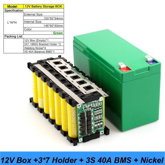
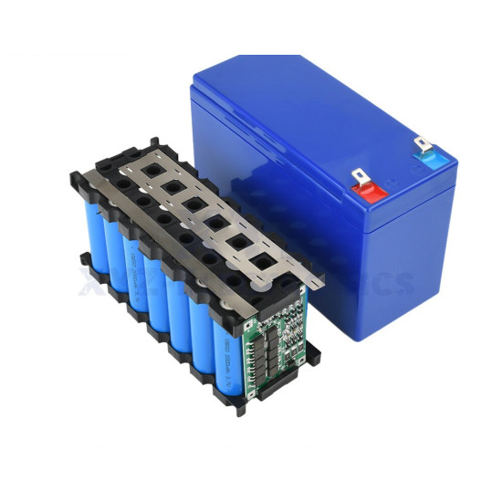
The 12V 18650 Battery Box Full DIY Kit provides hardware engineers, technicians, and electronics enthusiasts with a complete chassis and management architecture to assemble a high-density 12V (11.1V nominal / 12.6V peak) lithium-ion battery pack. Engineered to house exactly 21 individual 18650 cylindrical cells, this kit utilizes a 3S7P circuit topology—combining three series groups of seven parallel cells. This modular structure allows you to build a compact energy storage solution capable of replacing legacy 12V Sealed Lead-Acid (SLA) or AGM batteries while offering up to four times the energy density, significantly lower weight, and extended cycle life.
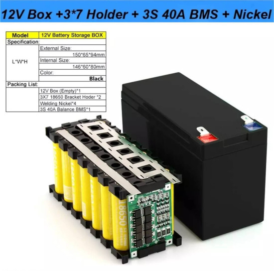
The included ABS plastic enclosure features external dimensions of 150mm x 65mm x 94mm, perfectly matching standard 12V 7Ah lead-acid battery form factors for direct retrofitting into UPS back-ups, alarm systems, and small electric mobility vehicles. Inside, custom 3S7P cell holders secure each cell, preventing short circuits caused by mechanical vibration while ensuring optimal thermal spacing for passive cooling during high-current charge and discharge cycles.
Integrated 3S 40A Balanced BMS Hardware Architecture
At the core of this DIY kit is an advanced 3S 40A Balanced Battery Management System (BMS). The BMS acts as the protective nerve center of the battery pack, monitoring cell health and managing electrical parameters to prevent thermal runaway, cell degradation, and dangerous over-current events. Operating across a working voltage window of 9.0V to 12.6V, the BMS delivers up to 40A continuous discharge current and up to 80A peak surge current, making it suitable for high-drain inductive loads such as DC motors and power inverters.
The BMS incorporates balance charging circuits that actively equalize voltage variations between the three series cell groups. During the final charging phase, when individual cell group voltages approach 4.20V, onboard bleed resistors dissipate excess energy from higher-voltage cells as low-level heat, allowing lower-voltage cells to catch up. This automated balancing preserves pack capacity and extends the operational lifespan of all 21 cells.
3S 40A BMS Onboard Terminal Pinout Definitions
Proper electrical integration requires accurate wiring between the 18650 cell matrix and the BMS solder pads. The pinout configuration for the onboard 3S 40A Balance BMS is defined as follows:
B- (Main Battery Ground): Solder connection point directly linked to the negative terminal of the first series cell group (0V reference point). This pad carries the full return discharge current of the entire pack.
B1 (First Series Balance Tap): Solder connection point positioned between the positive side of Series Group 1 and the negative side of Series Group 2. Nominal sensing voltage at this pad is 3.7V (4.2V fully charged).
B2 (Second Series Balance Tap): Solder connection point positioned between the positive side of Series Group 2 and the negative side of Series Group 3. Nominal sensing voltage at this pad is 7.4V (8.4V fully charged).
B+ (Main Battery Positive Voltage): Solder connection point directly linked to the positive terminal of the third series cell group. Nominal sensing voltage is 11.1V (12.6V fully charged). This pad handles the primary high-current supply pathway.
P- (Power Output / Charge Input Ground): Main external negative output terminal. All load return paths and charger negative leads connect here. The BMS switches this path off via low-internal-resistance MOSFETs during fault conditions (over-discharge, short circuit, or over-current).
P+ (Power Output / Charge Input Positive): Main external positive output terminal. Connects directly to external DC loads and 12.6V CC/CV lithium chargers. Tied directly to B+ within the BMS board layer.
Technical Specifications and Electrical Operating Parameters
Understanding the system threshold specifications is essential for safe system design:
Nominal Pack Voltage: 11.1V (3.7V per cell group)
Full Charge Cutoff Voltage: 12.6V (4.20V ± 0.05V per cell group)
Discharge Cutoff Voltage: 9.0V (3.00V ± 0.10V per cell group)
Continuous Discharge Current Limit: 40A (with adequate airflow / thermal dissipation)
Peak Instantaneous Discharge Current: 80A (duration under 100 milliseconds)
Continuous Overcharge Current Limit: 20A max charging current recommended
Overcharge Protection Detection Voltage: 4.25V ± 0.025V per series group
Over-discharge Protection Isolation Voltage: 2.50V ± 0.08V per series group
Over-current Protection Trigger Limit: 70A to 85A
Passive Balance Current: 41mA to 45mA per balance channel
Cell Matrix Configuration: 3 Series x 7 Parallel (21 Total 18650 Cells)
Deep-Dive Application Implementations and Wiring Pinout Guides
1. Custom E-Bike and Light Electric Vehicle Power Pack
This 12V 3S7P system can be connected in series or used standalone for 12V e-scooter, ride-on vehicle, or assist-motor applications. When interfacing with a 12V DC Motor Controller (e.g., 250W-350W brushed or brushless driver):
Pinout / Wiring Layout: Connect BMS terminal P+ to the Controller Positive Input Wire (typically red, 12AWG). Connect BMS terminal P- to the Controller Negative Input Wire (typically black, 12AWG). Install an inline 40A DC circuit breaker or MAXI blade fuse on the P+ line between the battery box and controller. Connect key-switch ignition leads directly across the low-current control circuit of the motor driver rather than interrupting the high-current P+ line.
2. High-Availability Uninterruptible Power Supply (UPS) for Networking Gear
Keep 12V fiber modems, Wi-Fi 6 routers, and PoE switches operational during utility power outages. Standard networking hardware requires continuous 12V DC input via 5.5mm x 2.1mm barrel jacks.
Pinout / Wiring Layout: Connect BMS terminal P+ to the positive input terminal of a 12V Automatic Switchover / Floating Charge Module and to the center pin of the DC 5.5x2.1mm output jack. Connect BMS terminal P- to the common ground rail of the switchover module and the outer sleeve pin of the DC barrel output jack. Route the external 12.6V CC/CV power adapter output across the input side of the switchover module to supply load current while maintaining trickle balance charging to the battery pack.
3. High-Torque Mobile Robotics and Autonomous Rover Platform
Power heavy-duty robotics platforms running dual high-torque DC motor drivers (such as Sabertooth 2x25 or BTS7960 43A bridges) along with step-down converters for microcontrollers.
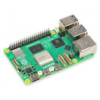
Pinout / Wiring Layout: Connect BMS terminal P+ to the Motor Controller V+ bus terminal and to the input of a Buck Converter (12V to 5V 5A). Connect BMS terminal P- to the Motor Controller GND bus terminal and Buck Converter GND input pin. The output pin (5V) of the Buck Converter supplies the Raspberry Pi or Arduino system board. This isolated topology prevents electrical noise generated by motor back-EMF spikes from resetting primary control logic.
4. Portable High-Fidelity Audio System (Class-D Amplifier Station)
Drive high-efficiency Class-D digital amplifiers (such as TPA3116D2 or TDA7498) for outdoor events and portable sound systems demanding clean, low-impedance transient current reserves.
Pinout / Wiring Layout: Connect BMS terminal P+ through a 15A SPST rocker switch to the VCC terminal of the Class-D amplifier board. Connect BMS terminal P- directly to the GND terminal of the amplifier board. Insert a 4700uF 25V low-ESR electrolytic capacitor directly across the VCC and GND terminals on the amplifier board to suppress voltage dips during heavy bass hits, maximizing acoustic headroom.
5. Field RC Flight Charger Station for LiPo Batteries
Model aircraft, drone, and RC car enthusiasts require field power to run multi-chemistry balance chargers (such as ISDT, ToolkitRC, or IMAX B6) at remote flying grounds.
Pinout / Wiring Layout: Terminate BMS output leads P+ and P- into an XT60 female chassis connector mounted directly through the top lid of the ABS enclosure. Solder BMS terminal P+ to the flat side terminal (Positive) of the XT60 connector using 12AWG silicone wire. Solder BMS terminal P- to the chamfered side terminal (Negative) of the XT60 connector. Field chargers plug directly into the XT60 port for low-resistance power extraction up to 400 Watts.
6. Solar-Charged Remote LED Lighting System
Construct a standalone off-grid power hub for sheds, workshops, or agricultural outbuildings requiring 12V LED lighting arrays and USB device charging.
Pinout / Wiring Layout: Connect BMS terminal P+ to the Battery Positive (+BATT) terminal of a 10A PWM/MPPT Solar Charge Controller. Connect BMS terminal P- to the Battery Negative (-BATT) terminal of the controller. Connect a 18V-20V VOC 50W Solar Panel across the SOLAR input terminals (+SOLAR / -SOLAR). Connect 12V LED strip light switches across the LOAD output terminals (+LOAD / -LOAD) of the solar controller to benefit from low-voltage load disconnect logic provided by the solar controller.
7. Emergency Backup Supply for 12V CPAP and Medical Accessories
Provide reliable overnight runtime for 12V-compatible CPAP machines (such as ResMed AirSense series via dedicated 12V DC converters) during emergency power cuts.
Pinout / Wiring Layout: Connect BMS terminal P+ to the center conductor pin of a heavy-duty female Automotive Cigarette Lighter Socket. Connect BMS terminal P- to the outer metal shell ground of the socket. Wire a digital LED Voltmeter display module across P+ and P- through a momentary push-button switch to allow on-demand monitoring of remaining battery capacity without continuous parasitic drain.
8. Remote Solar Telemetry and Outdoor IoT Edge Gateway Node
Supply continuous 24/7 power to outdoor environmental monitoring stations, weather sensors, and long-range LoRaWAN/cellular gateway equipment located in harsh off-grid environments.
Pinout / Wiring Layout: Connect BMS P+ and P- to the primary input lines of an intelligent DC-DC Programmable Power Distribution Board. Route P+ to an industrial DC-DC Buck-Boost regulator module to provide a ultra-stable, ripple-free 12.0V output rail to sensitive telemetry gear regardless of whether the battery pack is at 12.6V (full) or 9.0V (empty). Connect BMS balance leads to an external micro-telemetry ADC board to log cell-group health over LoRaWAN transmission.
Kit Components Included
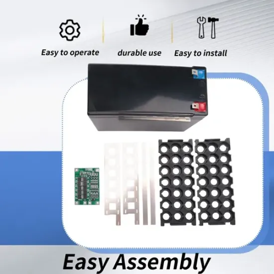
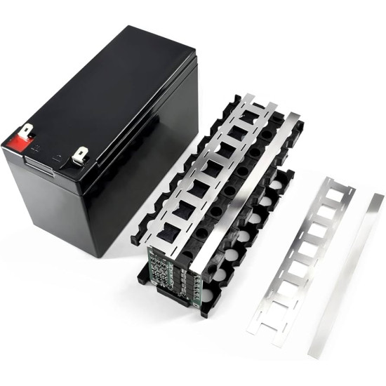
- 1x Heavy-Duty High-Impact ABS Plastic Case (150mm x 65mm x 94mm)
- 1x 3S 40A Continuous Balance Battery Management System (BMS) Board
- 2x 3S7P Precision Cell Spacers / Structural Holders
- 1x Set of Custom-Stamped High-Purity Nickel Strips for Spot Welding
Essential Assembly Tools and Safety Directives
Required Equipment (Not Included): 21x Unprotected 3.7V 18650 Li-ion cells (flat-top recommended), capacitive discharge battery spot welder, 60W+ temperature-controlled soldering iron, rosin-core solder, safety glasses, thermal insulating barley paper rings, and 12AWG flexible silicone wire.
CRITICAL SAFETY WARNING: Working with 18650 Lithium-Ion cells involves significant risk of electrical shorting, fire, or chemical thermal runaway if performed incorrectly. All 21 cells MUST be voltage-matched to within ±0.01V and have identical internal resistance profiles before physical spot-welding assembly. NEVER solder directly onto the caps or bases of 18650 cells; spot-welding via high-purity nickel strips is mandatory to prevent internal separator degradation. Always wear safety glasses and work over a non-conductive, non-flammable surface equipped with dry sand or a Class-D fire mitigation barrier nearby.