Menu
Your Cart
NOTICE: We have Fully discontinued physical walk-in customer service, RFQ, and LPO processing. Nerokas is now a FULLY DIGITAL ONLINE STORE, and our virtual assistant, Ginō AI, is here to help you navigate and checkout. Just ADD your Items to cart and type CHECKOUT on Ginō. Please note that corporate customers must register a corporate account to ensure proper Digital eTIMS/VAT processing.

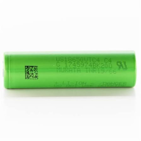
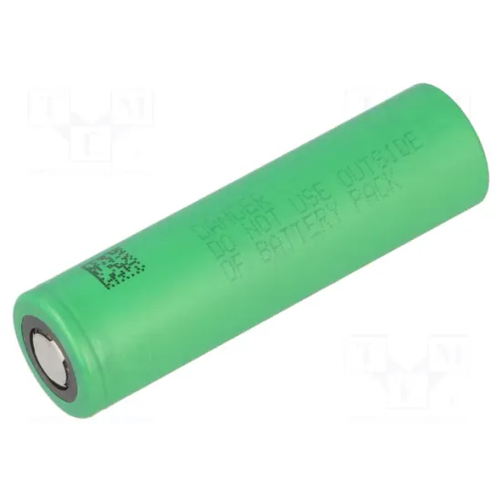
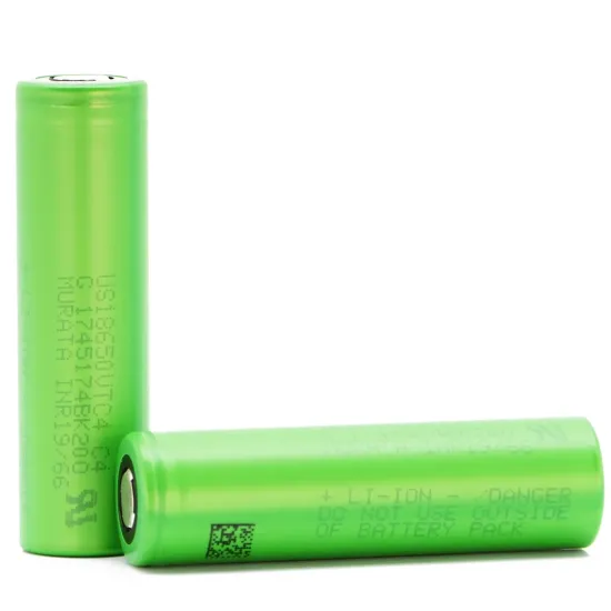
Sony Energy Devices - Murata INR18650 Cylindrical Li-ion Rechargeable Battery Cell

Sony Energy Devices - Murata INR18650 Cylindrical Li-ion Rechargeable Battery Cell
New
Sony Energy Devices - Murata INR18650 Cylindrical Li-ion Rechargeable Battery Cell
KES 550.00
  • Stock: In Stock
  • Model: Murata INR18650 Li
  • Weight: 46.50
  • Dimensions: 65.20 x 18.40 x 18.40
  • SKU: 4109

Architectural Overview and Electrochemistry

The Murata INR18650 (standard industry designation INR19/66) is an elite industrial-grade cylindrical lithium-ion secondary cell designed for critical applications demanding uncompromising energy density, sustained current delivery, and low thermal signatures. Originating from the foundational high-drain engineering developed by Sony Energy Devices and elevated through Murata precision manufacturing, this cell utilizes a Nickel-Manganese-Cobalt (LiNiMnCoO2 or NMC) cathode chemistry. The ternary cathode formulation balances high specific capacity from nickel, exceptional structural and thermal integrity from manganese, and low-resistance conductivity facilitated by cobalt. Integrated with an advanced synthetic graphite anode and an engineered separator membrane, the INR18650 achieves superior ionic conductivity across dynamic operational temperatures while substantially mitigating dendritic lithium growth during repeated high-rate charge and discharge cycles.

Internally, the cell incorporates a high-purity non-aqueous organic electrolyte supplemented with proprietary additives that stabilize the Solid Electrolyte Interphase (SEI) layer on the anode surface. This micro-engineered boundary layer prevents premature electrolyte consumption, elevates cycle endurance, and keeps internal alternating-current impedance (AC-IR) to nominal milliohm levels. As a result, the Murata INR18650 minimizes resistive heating (I2R losses) during aggressive load transitions, maximizing thermal headroom in densely packed multi-cell battery enclosures and safeguarding system longevity.

Comprehensive Technical Specifications and Operating Parameters

Operating at a standard nominal voltage of 3.6V to 3.7V, the cell exhibits a steep, predictable open-circuit voltage discharge curve, terminating at a safe discharge cut-off threshold of 2.5V (or 2.0V under qualified industrial BMS profiles). Charging is conducted via a standard Constant Current / Constant Voltage (CC/CV) protocol up to a precision ceiling of 4.20V plus or minus 0.05V. The cell supports continuous high-rate discharge current profiles, retaining structural stability and cell voltage under rapid load conditions without tripping internal mechanisms or initiating destructive localized heating. Its internal resistance, consistently measured below 15 to 30 milliohms (depending on exact sub-variant and state-of-charge), allows high transient peak pulse currents indispensable for inductive load startups, electric motors, and wireless transmitter bursts.

Thermal envelopes for the Murata INR18650 are strictly delineated to optimize safety and cycle life. Standard charging parameters require ambient operational windows between 0 degrees Celsius and 45 degrees Celsius to avert irreversible lithium plating, while operational discharge occurs seamlessly from -20 degrees Celsius to +60 degrees Celsius. Under regulated storage parameters (recommended 3.6V to 3.8V state of charge at 20 degrees Celsius), the self-discharge rate remains below 2% to 3% per month, ensuring lengthy shelf integrity and minimal state-of-health degradation during transport and inventory staging.

Mechanical Design, Venting, and Safety Interlocks

Housed in a drawn nickel-plated steel casing meeting precise mechanical tolerances, the Murata INR18650 measures approximately 18.35 mm in diameter and 65.20 mm in axial length. The outer can acts as the physical chassis and electrical negative terminal, offering substantial mechanical resistance against puncture, crushing, vibration, and dynamic environmental shock. Hermetically sealed using an automated crimping process, the positive header contains an elastomeric gasket and a multi-layered safety stack comprised of a Current Interrupt Device (CID) and a directional pressure relief exhaust vent.

In the event of an abnormal internal pressure spike caused by electrical abuse, external thermal exposure, or internal shorting, the integrated CID disc actuates upward, physically disconnecting the internal electrode assembly from the external positive terminal button. Concurrently, should pressure continue to elevate beyond critical limits, the calibrated rupture vent bursts cleanly to release gases in a controlled, axial trajectory, dramatically decreasing the probability of violent structural enclosure rupture or catastrophic thermal propagation across neighboring cells in a pack array.

Terminal Architecture and Pinout Configuration

The Murata INR18650 adheres to standardized cylindrical lithium-ion cell topology, featuring distinct positive and negative electrical interfaces integrated across its form factor:

Positive Terminal (Cathode Contact): Located at the top end of the cell, the positive cap is presented as a flat-top (or button-top depending on pack assembly variant) contact plate featuring four or three radial exhaust vents underneath the terminal lip. This terminal is electrically connected to the internal aluminum current collector foil via the integrated CID assembly. It serves as the output node during discharge and the input node during CC/CV charge operations.

Negative Terminal (Anode Contact): Formed by the broad, planar steel base of the cell can, the negative terminal is metallically continuous with the outer sidewalls of the cell. Internally, the copper current collector foil is ultrasonically welded to this base. The wide, flat footprint provides a low-resistance contact interface optimized for automated resistance spot welding or direct connection to industrial beryllium copper leaf springs.

Polarity Boundary and Insulation: The cylindrical sidewalls and the peripheral shoulder of the positive terminal are shrouded in a heavy-duty polymer heat-shrink wrap, typically accompanied by a fish-paper or Kapton insulation ring around the positive shoulder. This critical insulating barrier prevents external conductors, welded nickel busbars, or structural chassis elements from short-circuiting between the raised positive cap and the negative steel rim exposed directly beneath the crimp perimeter.

Application Use-Cases

1. Electric Micro-Mobility and Light Electric Vehicles: Ideal for low-profile, high-capacity traction battery packs in electric bicycles, cargo trikes, and standing electric scooters. The high current capability and stable thermal signature ensure sustained torque generation when accelerating and hill-climbing without inducing damaging thermal gradients across 10S to 14S pack architectures.

2. Unmanned Aerial Vehicles (UAVs) and Autonomous Drones: Employed in fixed-wing and multirotor commercial survey drones requiring continuous medium-to-high discharge current coupled with superior gravimetric energy density. The cells provide significantly longer operational lifespans and greater mechanical abuse resistance compared to soft-pack lithium polymer alternatives.

3. Industrial Field Robotics and Automated Guided Vehicles (AGVs): Powers warehouse automated transport systems, collaborative warehouse robots, and autonomous floor scrubbers. The low self-discharge and high cycle life ensure continuous multi-shift operations, rapid turnaround charging cycles, and minimal maintenance-related downtime.

4. Professional Cordless Power Tools and Fasteners: Designed to handle the aggressive, discontinuous current spikes found in commercial rotary hammers, circular saws, and industrial nailers. The low internal AC resistance of the cell minimizes internal voltage droop during high-torque stalls, delivering sustained motor performance.

5. Remote Telemetry, Environmental Monitoring, and IoT Gateways: Provides multi-year autonomous backup or primary power for edge computing platforms, seismic monitors, weather stations, and long-range cellular IoT hubs. Paired with localized solar charging panels, the cell maintains wide thermal operability and dependable cycling over years of unattended deployment.

6. Portable Emergency Medical Equipment: Deployed in mobile defibrillators, portable mechanical ventilators, infusers, and rugged field diagnostics. The precise discharge characteristics, proven failure-mode mitigations, and stringent Murata quality standards guarantee instantaneous peak-power readiness in life-critical scenarios.

7. Off-Grid Solar Energy Storage Systems (ESS) and Micro-Inverters: Assembled into modular home or commercial battery racks. When paired with high-voltage battery management systems, parallel and series groupings of the INR18650 deliver reliable frequency regulation, solar peak shaving, and nocturnal energy shifting with exceptional round-trip coulombic efficiency.

8. Mission-Critical Backup Power and Datacenter Rack UPS Systems: Forms the core reserve architecture for localized, rack-mount uninterruptible power supplies (UPS). In high-density computing and server environments, the high discharge rate allows compact modular UPS frames to provide vital ride-through power until diesel auxiliary generators synchronize with the main bus.

Interconnection, Pack Manufacturing, and Spot-Welding Guidelines

When integrating the Murata INR18650 into multi-cell series-parallel matrices, direct soldering with handheld soldering irons is strictly prohibited, as the localized thermal shock damages the polymer separator and compromises the integrity of the CID seals. Assembly must be carried out using capacitive discharge, alternating-current pulse, or laser spot welding utilizing pure nickel or copper-nickel composite busbar ribbons. Nickel strips of appropriate cross-sectional area should be selected to manage targeted root-mean-square (RMS) current without creating parasitic heat sinks along the cell terminations.

To guarantee complete electrical and physical safety, all custom pack designs must incorporate a Battery Management System (BMS) with individual cell-level monitoring for over-voltage (OVP), under-voltage (UVP), over-current charge/discharge, and short-circuit protection. Dual-point or multipoint NTC thermistors should be mechanically referenced to the core of the pack assembly to dynamically throttle current delivery when localized pack temperatures exceed recommended operational limits.

Ginō Ginō AI - Nerokas AI Assistant
✕
Jambo! I am Ginō, a Nerokas AI Assistant and Africa's best Open Hardware Facilitator AI agent here to help. In order to serve you better and to help me give you accurate shipping estimates as we begin, could you please tell me your name and your location/city?

You can also ask about any hardware or type I'd like to order, I am looking for..., you can also LIST all SKUs & Quantity of desired items from our website here for me to help you Checkout automatically at anytime to fast-track your requests and orders.