Menu
Your Cart
NOTICE: We have Fully discontinued physical walk-in customer service, RFQ, and LPO processing. Nerokas is now a FULLY DIGITAL ONLINE STORE, and our virtual assistant, Ginō AI, is here to help you navigate and checkout. Just ADD your Items to cart and type CHECKOUT on Ginō. Please note that corporate customers must register a corporate account to ensure proper Digital eTIMS/VAT processing.

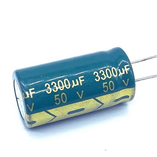
3300uF 50V Radial Aluminum Electrolytic Capacitor

3300uF 50V Radial Aluminum Electrolytic Capacitor
New
3300uF 50V Radial Aluminum Electrolytic Capacitor
KES 150.00
  • Stock: In Stock
  • Model: 3300uF 50V Radial Aluminum Ele
  • Weight: 14.50
  • Dimensions: 18.00 x 18.00 x 35.50
  • SKU: 1625

Comprehensive Engineering Overview

The 3300uF 50V Radial Aluminum Electrolytic Capacitor represents a core building block in modern power electronics, designed specifically to address high energy density storage, low-frequency ripple suppression, and bulk decoupling requirements. Operating at a nominal capacitance of 3300 microfarads with a maximum working voltage threshold of 50 volts direct current, this component manages heavy energy transfers in demanding industrial, consumer, and automotive circuit designs. The internal geometry relies on high-purity etched aluminum foil coupled with an advanced liquid electrolyte matrix to maximize active surface area within an optimized physical footprint. This structural optimization ensures minimal parasitic Equivalent Series Resistance and minimized Equivalent Series Inductance, which directly correlates to superior transient response characteristics when the capacitor is subjected to high-rate dynamic loads.

Aluminum electrolytic capacitors of this caliber are engineered to operate continuously across an extended thermal spectrum spanning from minus 40 degrees Celsius to plus 105 degrees Celsius. This broad operational window provides resilience against thermal throttling, making it an exceptional candidate for enclosures with limited convection cooling or active forced-air ventilation. With a standard commercial tolerance rating of plus or minus 20 percent, the component delivers dependable capacitance metrics even under harsh thermal stress, preserving rail stability, reducing switching ripple voltage, and safeguarding downstream semiconductor junctions from damaging overvoltage conditions.

Dielectric Physics and Internal Construction

Internally, this radial capacitor consists of high-purity aluminum anode and cathode foils wound tightly together with a specialized porous separator paper saturated with an advanced conductive liquid electrolyte. The dielectric medium itself is not a physical insert but a microscopic layer of aluminum oxide (Al2O3) formed electrochemically over the micro-etched surface of the anode foil. This anodic oxidation yields an exceptionally thin dielectric barrier with high dielectric strength, delivering substantial capacitive yield per unit volume. The cathode foil acts primarily as an electrical contact to the liquid electrolyte, which serves as the true functional cathode conforming precisely to the etched valleys of the anode.

The wound element is hermetically sealed within a rugged, drawn-aluminum cylindrical canister. At the bottom, a heavy-duty synthetic rubber seal provides mechanical containment and prevents the gradual dry-out of volatile liquid electrolyte solvents over long operational lifespans. The upper dome of the aluminum can incorporates stamped score lines, forming an engineered pressure relief safety vent. In the rare event of electrical overstress, continuous overvoltage, or reverse polarization, the internal pressure generated by gas evolution safely ruptures the scored vent rather than causing a catastrophic casing explosion, maintaining strict physical safety boundaries for adjacent board-level electronic components.

Electrical Dynamics, Ripple Current, and Lifespan Derating

The operational endurance of the 3300uF 50V electrolytic capacitor is governed by the thermal stresses generated by internal resistive losses. The continuous alternating current traversing the device induces I-squared-R heating across its internal Equivalent Series Resistance. This capacitor is engineered with a high ripple current threshold, allowing it to sustain substantial RMS ripple current at 100 kilohertz and 120 hertz without exceeding its critical internal core temperature. Low dissipation factor values ensure minimal phase shift and minimized active power dissipation within the dielectric lattice.

Component lifespan reliably mirrors the classic Arrhenius rate rule, wherein every ten degrees Celsius drop in core operating temperature beneath the maximum rated limit of 105 degrees Celsius approximately doubles the functional operational life of the unit. Designers operating this component on a 24V or 36V continuous DC bus at ambient temperatures of 65 degrees Celsius can achieve service lifetimes exceeding several tens of thousands of continuous operational hours. Additionally, the component demonstrates robust self-healing characteristics: localized microscopic defects within the aluminum oxide dielectric layer are continuously rehabilitated by electro-chemical reactions driven by the liquid electrolyte during standard forward-biased operation.

Pinout and Lead Polarity Configuration

The component is manufactured in a standard polarized two-lead radial orientation. Polarized electrolytic capacitors require precise PCB orientation, as continuous exposure to reverse bias will cause dielectric breakdown, elevated internal gas generation, and eventual safety vent activation. Proper alignment is easily verified using tactile and visual lead indicators.

Lead 1: Cathode (Negative Lead). Geometrically, this is the shorter metal lead extending from the rubber base. On the cylindrical outer sleeve, the cathode is explicitly marked by a high-contrast vertical stripe containing minus symbols running the entire length of the polyvinyl chloride insulating jacket.

Lead 2: Anode (Positive Lead). Geometrically, this is the longer metal lead extending from the rubber base. It must be connected to the higher electrical potential in single-supply circuits or the ground reference in negative rail configurations. The outer sleeve remains unmarked on this side to indicate the positive terminal.

Application Deep-Dive: 8 Dedicated Engineering Use Cases

1. Switch-Mode Power Supply (SMPS) Secondary Output Rectification: In forward, flyback, and half-bridge SMPS designs, high-frequency rectification generates severe output voltage ripple. Positioned immediately downstream of the secondary Schottky barrier diode or synchronous MOSFET bridge, this 3300uF 50V capacitor acts as a low-impedance bulk filter, absorbing peak switching currents, suppressing ripple amplitude below 50 millivolts, and maintaining strict line regulation under dynamic consumer and industrial loads.

2. High-Fidelity Audio Power Rail Decoupling and Ripple Suppression: In Class-AB and Class-D audio power amplifiers, dynamic current demands peak rapidly during low-frequency bass reproduction. Placing this component directly on the split-rail or single-ended supply lines prevents power rail sagging, keeps transient intermodulation distortion minimal, and filters out residual 100Hz or 120Hz mains hum induced by bridge rectifiers, ensuring clean acoustic performance.

3. DC-DC Buck and Boost Converter Input and Output Reservoir Staging: High-current step-down and step-up converters produce high input discontinuous currents. Serving as an input reservoir, this capacitor dampens high di/dt current pulses drawn from upstream supplies, reducing electromagnetic emissions across input cabling and preventing inductive switching spikes from exceeding the input breakdown thresholds of converter ICs.

4. High-Torque Brushless DC (BLDC) Motor Controller Inverters: In multi-phase BLDC and Permanent Magnet Synchronous Motor (PMSM) drives, rapid phase commutations generate significant back-EMF spikes and severe current transients. This 3300uF 50V capacitor absorbs the inductive energy kickback from motor windings during regenerative braking, stabilizing the internal DC link voltage bus and protecting sensitive power MOSFET or IGBT stages from transient overvoltage failure.

5. Solar Photovoltaic Maximum Power Point Tracking (MPPT) Buffer: Solar micro-inverters and charge controllers require stable intermediate direct current storage to permit accurate impedance matching algorithms. This capacitor serves as an intermediary energy storage reservoir, dampening the rapid fluctuations caused by localized solar panel shading and maintaining the continuous current flow necessary for maximum energy harvesting efficiency.

6. Industrial Uninterruptible Power Supply (UPS) Hold-Up Capacitance: In mission-critical automation systems, momentary mains power brownouts can induce microprocessor resets. Integrated into the intermediate DC bus of a UPS system, the energy stored inside this 3300uF capacitor supplies the crucial milliseconds of hold-up time required for control logic to systematically execute emergency data storage routines or transfer input rails safely to battery bank power.

7. Automotive Transient Suppressor and Inductive Kickback Snubbing: In 12V and 24V vehicular auxiliary sub-systems, inductive switching of heavy electromechanical relays, alternators, and solenoids produces severe voltage transients such as load dump spikes. Applied as a transient suppression reservoir, this capacitor clamps sudden electrical surges, stabilizes local microcontroller supplies, and filters destructive inductive noise from the vehicle harness.

8. RF Transceiver Pulsed Load Compensation and Voltage Droop Mitigation: High-power cellular, VHF, and microwave power amplifier modules pull intermittent, high-amplitude current pulses during transmission bursts. Installing this capacitor adjacent to the RF amplifier module supplies instantaneous burst charge, preventing rail voltage droop that would otherwise cause frequency pulling, spectral regrowth, and unexpected transceiver brownouts.

Installation Guidelines and PCB Layout Best Practices

To extract optimal high-frequency performance and achieve rated operational longevity, careful circuit board layout practices must be adhered to. Designers should minimize parasitic track inductances by placing this capacitor as physically close as possible to the primary load or switching semiconductor. Traces feeding the anode and cathode must be executed using wide copper pours or polygon fills rather than narrow circuit traces, ensuring the low ESR benefits of the component are not negated by trace resistance.

Thermal management is equally crucial during PCB layout. The capacitor must not be situated directly adjacent to major heat-dissipating components such as power transformers, heatsinks, power resistors, or TO-220 semiconductor packages. Radiated and conducted thermal energy from these structures accelerates liquid electrolyte evaporation, significantly reducing operational lifetime. During wave or manual soldering operations, thermal profiles must respect the component threshold limits, ensuring dwell times at standard solder temperatures do not heat the internal rubber seal beyond its mechanical tolerance limits.

Ginō Ginō AI - Nerokas AI Assistant
✕
Jambo! I am Ginō, a Nerokas AI Assistant and Africa's best Open Hardware Facilitator AI agent here to help. In order to serve you better and to help me give you accurate shipping estimates as we begin, could you please tell me your name and your location/city?

You can also ask about any hardware or type I'd like to order, I am looking for..., you can also LIST all SKUs & Quantity of desired items from our website here for me to help you Checkout automatically at anytime to fast-track your requests and orders.