Out Of Stock


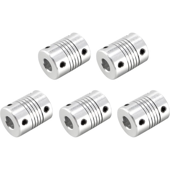
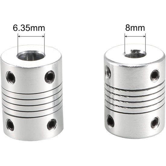
Flexible Coupler 6.35mm to 8mm
KES 200.00
- Stock: Out Of Stock
- Model: Coupler 6.35mm to 8mm
- Weight: 16.50g
- Dimensions: 25.00mm x 19.00mm x 19.00mm
- SKU: 3210
Your shopping cart is empty!


The 6.35mm to 8mm flexible beam shaft coupler is a precision-engineered motion transmission component designed to mechanically link rotating shafts with disparate diameters while compensating for systematic angular, parallel, and axial misalignments. Fabricated from high-tensile aircraft-grade aluminum alloy, this structural element exhibits an exceptional balance between lightweight rotational inertia and robust torsional stiffness. Helical beam couplings are manufactured using a continuous, precision-machined spiral cut through a cylindrical aluminum blank. This continuous flexure configuration allows the coupling to smoothly transmit rotary motion with virtually zero backlash, isolating delicate motor bearings from bending moments caused by runout or structural frame deflection.
In high-precision mechatronics, motion control loops require uncompromising fidelity between the driving actuator, such as a stepper or brushless DC motor, and the driven assembly, such as a ball screw, lead screw, or rotary encoder. Shaft misalignment is an inevitable byproduct of manufacturing tolerances, thermal expansion, frame distortion, and mechanical assembly variances. Rigid couplings, when subjected to these concentricity errors, transfer severe radial and bending loads directly onto internal motor bearings and drive nuts, leading to premature bearing failure, periodic binding, lost steps, and high-frequency acoustic noise. This 18mm outer diameter, 25mm length flexible coupling mitigates these destructive forces by absorbing kinetic compliance within its elastic spring beams, ensuring pure torsional transmission with high rotational accuracy.
Constructed from homogeneous, structural 6061-T6 aluminum alloy, this coupling benefits from the superior strength-to-weight ratio intrinsic to tempered magnesium-silicon aluminum blends. The material undergoes precipitation hardening, granting it a yield strength typically exceeding 270 MPa (39,000 psi) and an ultimate tensile strength exceeding 310 MPa. This structural rigidity ensures that the helical spring beams withstand repeated cyclic loading, torsional reversing cycles, and continuous dynamic stresses without undergoing plastic deformation.
Furthermore, aluminum 6061 provides low rotational mass. Minimizing rotational inertia along a precision drive train is vital for maximizing system bandwidth, allowing stepper and servo systems to achieve higher acceleration profiles and lower settling times without stalling or drawing excessive current. The coupling surface is treated with an electrochemical clear anodization layer. Anodizing creates an integral sapphire-hard aluminum oxide surface that provides formidable resistance against atmospheric oxidation, chemical wear from industrial lubricants, and particulate abrasion, maintaining surface integrity and bore tolerance stability across thousands of operating hours.
The asymmetric bore design features a 6.35mm (standard 1/4 inch) internal diameter on one end and an 8.00mm metric internal diameter on the opposing end. The 6.35mm bore conforms precisely to imperial shaft profiles frequently encountered on American-standard NEMA 23 stepper motors, optical encoder shafts, and custom planetary gearbox outputs. Conversely, the 8.00mm bore serves as an industry standard for European and Asian motion components, integrating seamlessly with T8 lead screws, 8mm ground linear rods, ISO-compliant ball screws, and standard metric servo shafts. Both internal bores are reamed to an H7/H8 standard manufacturing tolerance, ensuring a high-concentricity sliding fit that prevents eccentric shaft clamping.
The central functional zone consists of a single-piece helical slit cut along a cylindrical helix. As torque is introduced into the driving shaft, the helical coils undergo tensile and compressive elastic deformation across their cross-sections. When angular misalignment occurs (up to 2 degrees) or parallel lateral offset takes place (up to 0.2mm), the beam elements flex predictably, absorbing the positional error without transmitting side loads. Axial compliance allows the coupling to tolerate dynamic shaft end-float of up to 0.5mm, safeguarding sensitive motor encoders and shaft retaining rings from axial pre-load destruction.
Fastening of the shafts within the coupling bores is achieved via precision internal threaded holes hosting high-grade metric set screws (grub screws). Unlike simple frictional slips, these set screws are oriented orthogonally at 90-degree radial displacements at each hub end, delivering positive dual-point mechanical clamping against the motor and lead screw shafts. When engaged with flat-profile shafts (D-shafts), the primary set screw tightens against the flat plane to form a positive mechanical interlock, eliminating slip under sudden reversing acceleration, while the second screw provides concentric centering force on the circular shaft profile.
The structural layout of the coupling maintains a clean, uniform 18mm outer profile across its entire 25mm length. This compact envelope ensures minimal sweep radius, preventing mechanical interference within tight 3D printer vertical extrusions, enclosed CNC motor mounts, robotic joint casings, and miniature laboratory instrument chassis. The internal bore depth is balanced at approximately 9mm to 10mm per side, separated by the central relief chamber formed by the helical slit, ensuring that shaft insertion depth can be precisely gauged to avoid encroaching into the active flexure zone.
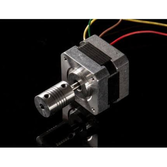
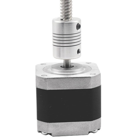
In high-resolution FDM (Fused Deposition Modeling) 3D printers, the Z-axis drive mechanism commonly pairs a NEMA 17 or NEMA 23 stepper motor featuring a 6.35mm output shaft with an 8mm multi-start T8 trapezoidal lead screw. Because structural vertical frame extrusions rarely exhibit absolute perpendicularity to the motor mounting plane, a rigid coupling forces the bent or eccentric lead screw to wobble laterally, telegraphing a continuous, cyclic sinusoidal defect onto the print surface known as Z-banding or Z-wobble. Integrating this 6.35mm to 8mm flexible beam coupler isolates the eccentric lateral runout of the lead screw from the motor shaft, enabling smooth vertical carriage translation and producing impeccably smooth, layer-consistent external perimeter finishes.
Desktop CNC milling machines and PCB prototyping routers demand high axial stiffness combined with localized angular compliance to withstand high-frequency cutting vibrations. Motor mount plates on desktop gantries frequently experience thermal expansion and vibration-induced micro-shifting during aggressive feed rates. By linking a 1/4-inch NEMA 23 stepper motor to an 8mm precision rolled ball screw (such as an SFU1204 or SFU1004 with turned 8mm journals), this coupler absorbs spindle chatter and vibration harmonics, preventing high-frequency mechanical shock from back-driving into the stepper rotor and corrupting positional tracking during precise micro-milling operations.
Articulated robotic manipulators often rely on distributed drive architectures where high-torque brushless outrunner motors or planetary gearmotors are coupled to joint shafts or harmonic drive wave generators. In custom-built end-effector linkages, a 6.35mm motor shaft must regularly interface with an 8mm joint pivot or rotary sensor shaft. The lightweight 6061-T6 aluminum composition keeps overall arm link mass to a minimum, directly reducing joint inertia and motor thermal load while providing zero-backlash torque transmission essential for repeatable path trajectory following and precise spatial tool positioning.
Automated analytical chemistry and microfluidics instrumentation require micro-liter liquid dosing via motorized syringe pumps. In these systems, positional repeatability down to single-digit microns is imperative. Stepper motors equipped with 6.35mm shafts actuate an 8mm ultra-fine pitch lead screw that drives the syringe plunger. The zero-backlash characteristic of the helical beam coupler ensures that directional reversals introduce no dead-band hysteresis into the fluidic dispensing profile, preventing volume delivery errors and ensuring consistent analytical reagent titrations.
Precision instrumentation often requires external absolute or incremental rotary encoders to monitor the rotational state of heavy load shafts. Direct mechanical connection between an 8mm system drive shaft and a delicate 6.35mm optical encoder spindle can easily exceed the encoder maximum permissible radial and axial bearing load ratings, leading to cracked glass discs or optical sensor misalignment. Utilizing this flexible beam coupling accommodates runout between the encoder body and machine frame, ensuring smooth rotational tracking without transmitting destructive external shaft loads into the sensitive encoder assembly.
Surface Mount Technology (SMT) component placement systems operate under aggressive acceleration and deceleration profiles, continuously navigating sub-millimeter components to high-density circuit boards. The rapid directional cycles introduce torsional shock loads through the drive train. Bridging a 6.35mm servo drive shaft to an 8mm ground lead screw with this helical beam coupler absorbs the high-frequency inertial spikes at transition points, damping motor resonance and suppressing ringing artifacts that would otherwise extend settling time during high-speed feeder cycles.
Pan-tilt tracking mounts for remote sensing cameras, astronomical optics, and laser communication platforms rely on ultra-smooth, continuous rotation devoid of mechanical detent cogging or binding. When mating compact 6.35mm actuator shafts with 8mm elevation and azimuth drive shafts, this aluminum coupling absorbs mechanical thermal growth across broad outdoor temperature ranges (-40C to +85C) without losing its coaxial gripping force, preventing mechanical binding that would otherwise destabilize optical tracking integrity.
In web handling, tensioning rollers, and packaging bottle-capping stations, continuous duty cycles demand mechanical linkages that require zero maintenance and zero lubrication. Unlike jaw-type couplings that rely on elastomer spiders that degrade, embrittle, and shred under petrochemical exposure, or universal joints that demand routine grease lubrication, this one-piece metallic beam coupler contains no sliding surfaces or perishable polymers. It operates continuously in dusty, contaminated, or grease-rich packaging environments with zero operational maintenance requirements.


To extract optimal performance and ensure an indefinite fatigue life from the helical flexible beam coupler, meticulous installation protocols should be observed. First, the driving and driven shafts must be inspected for burrs, scoring, or out-of-round profiles. Both shafts should be thoroughly cleaned and degreased before insertion into the coupling bores. Shafts should be inserted into the coupling hubs to a depth of approximately 8.5mm to 9.5mm, ensuring adequate contact length for the set screws while strictly preventing the shaft ends from bottoming out or protruding into the central cut flexure section. Shaft intrusion into the helical cut zone completely compromises the coupling ability to flex, resulting in localized shear fracture of the aluminum spring coils.

When securing the set screws, a medium-strength anaerobic thread-locking fluid (such as blue Loctite 242 or equivalent) should be applied to the threads to prevent loosening induced by operational vibrations. The set screws should be tightened incrementally using a precision hex key to avoid stripping the internal sockets. When mating with flat D-shafts, verify that the primary set screw sits squarely perpendicular against the flat machined surface. Finally, although the coupling gracefully absorbs up to 2 degrees of angular offset and 0.2mm of parallel displacement, aligning the shafts as close to true coaxial alignment as feasible using a dial indicator or alignment gauge will significantly minimize cyclic stress concentrations, ensuring indefinite fatigue resistance and silent, ultra-smooth motion control.
Ginō AI - Nerokas AI Assistant