


- Stock: In Stock
- Model: TXS0108E 8 Channel Logic Level Converter Module
- SKU: 3429

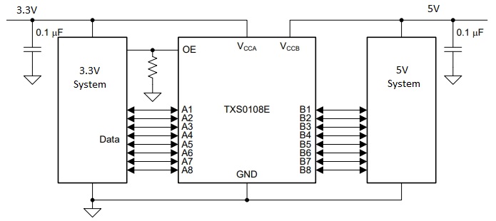
The TXS0108E 8-Ch Logic Level Converter Module is a bi-directional device for converting signals between 3.3V and 5V logic systems.
PACKAGE INCLUDES:
- TXS0108E 8-Channel Logic Level Converter Module
- Qty 2 -10-pin male header strips
KEY FEATURES OF TXS0108E 8-CH LOGIC LEVEL CONVERTER MODULE:
- 8 channels can convert up to 8 logic signals
- Converts voltage levels between 1.2 to 3.6V and 1.65 to 5.5V systems
- Bi-directional with automatic direction control
- Each channel operates independently
- Optimized for open-drain applications like I2C, but can also work in push-pull applications
- Output enable allows outputs to be disabled
This module is typically used to connect 3.3V and 5V logic signals together, but it is compatible with many different logic voltages. The low (A) side can handle 1.2 to 3.6V logic levels. The high (B) side can handle 1.65 to 5.5V logic levels.
There are 8 bi-directional channels which is especially useful for buses that pass data in both directions. It can also be used for unidirectional signals like SPI.
The TXS0108 is designed for open-drain applications like I2C and includes dynamic pull-up / pull-down resistors, but it can be used in standard CMOS push-pull translation as well.
The output enable (OE) can be tied to Vcca to enable the outputs at all times. If it is desirable to have the device power up with the outputs disabled, use a pull-down resistor to ground which keeps the outputs off until it is enabled by driving the pin HIGH under MCU control. Disabling the OE is also useful for ultra low power applications since it shuts off the pull-up resistors and drops the idle current to a few uA.
When hooking up power, the lower voltage side must be connected to the ‘A’ side. This will typically be 3.3V. The higher voltage side which is typically 5V should be connected to the ‘B’ side.
The device is not affected by power supply sequencing during power up, so having one side powered and the other side unpowered will not damage the device.
Module Operation
To use the module, you hook up the two voltages that you want to convert between to the A (low Voltage) and B (High Voltage) inputs. The higher voltage is always connected to the B side.
If using with an Arduino to interface to a 3.3V module, you would typically connect the 3.3V output of the Arduino to the Low Voltage Vcca input and the 5V output of the Arduino to the High Voltage Vccb input.
The ground connection should be common with the ground of both logic systems.
You then hook-up the lower voltage logic signals to the A1-A8 pins and the higher voltage logic signals to the corresponding B1-B8 pins (A1 connects to B1, etc) and you are set to go. There is no direction control required for the bi-directional functionality.
The OE pin needs to be pulled to Vcca if the outputs will always be enabled. Add a pull down resistor of 1K or so if you want the device to come up disabled until the uC enables it by driving the pin HIGH.
The module comes with 2 strips of male headers. These can be soldered on for use on a breadboard, or you can attach wires directly to the board depending on what your application requires. If soldering the headers on, it is recommended to insert the headers into a solderless breadboard first to hold them in alignment while soldering.
Module Connections
The board has the following I/O connections:
- VA = Low voltage. Must be lower voltage than VB. Typically tied to 3.3V
- VB = High voltage. Must be higher voltage than VA. Typically tied to 5VV
- GND = Ground. Should be common to both voltage systems.
- A1 / B1 = Channel 1
- A2 / B2 = Channel 2
- A3 / B3 = Channel 3
- A4 / B4 = Channel 4
- A5 / B5 = Channel 5
- A6 / B6 = Channel 6
- A7 / B7 = Channel 7
- A8 / B8 = Channel 8
- OE = Output Enable. Active HIGH.
ASSEMBLING THE MODULE
The board ships with the male headers loose. This provides maximum flexibility depending on how the board will be used or they can be replaced with other types of connectors such as female headers.
To ensure good alignment during soldering first insert the loose headers into a solderless breadboard. The board can then be placed on top of the headers and easily soldered in place.
OUR EVALUATION RESULTS:
These modules work very well when used correctly and are an easy way to implement level shifting for a number of applications. They operate faster than the common MOSFET level shifters and the 8 channels allows you to convert a complete 8-bit bus or multiple signals such as converting an I2C bus and several other logic signals.
Because these devices are auto-direction sensing with internal logic that senses and switches the direction automatically, they are typically not a good option for converting between something like a 3.3V MCU and GPIO where the I/O pin may be randomly connected to something like a switch or LED as erratic operation can occur.
TECHNICAL SPECIFICATIONS
| Operational Ratings | ||
| Vcca | Low Side | 1.2V – 3.6V |
| Vccb | High Side | 1.65V – 5.5V |
| Data Rate | Push-pull | 20Mbps |
| Open-drain | 2Mbps | |
| Dimensions | L x W (PCB) | 26 x 17mm (1″ x 0.7″) |
| Footprint | DIP-20 on 0.5″ center | |
| Datasheet | Texas Instruments | TXS0108E |
