Menu
Your Cart
NOTICE: We have Fully discontinued physical walk-in customer service, RFQ, and LPO processing. Nerokas is now a FULLY DIGITAL ONLINE STORE, and our virtual assistant, Ginō AI, is here to help you navigate and checkout. Just ADD your Items to cart and type CHECKOUT on Ginō. Please note that corporate customers must register a corporate account to ensure proper Digital eTIMS/VAT processing.

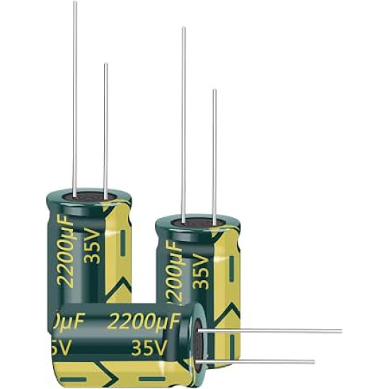
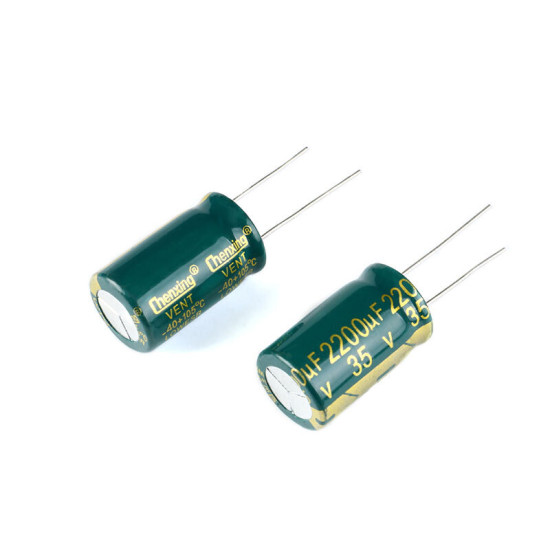
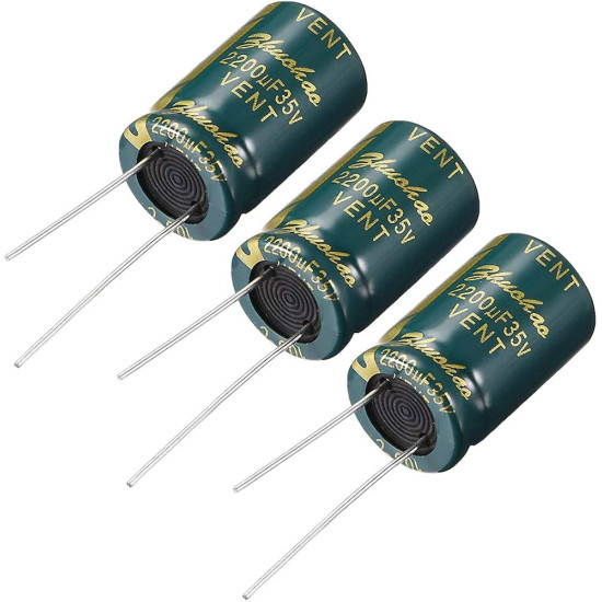
2200uF 35V Radial Aluminum Electrolytic Capacitor

2200uF 35V Radial Aluminum Electrolytic Capacitor
New
2200uF 35V Radial Aluminum Electrolytic Capacitor
KES 50.00
  • Stock: In Stock
  • Model: 2200uF 35V Radial Aluminum Ele
  • Weight: 5.40
  • Dimensions: 12.50 x 12.50 x 25.00
  • SKU: 42

Comprehensive Engineering Overview

The 2200uF 35V Radial Aluminum Electrolytic Capacitor is engineered to meet the demanding requirements of high-performance power conversion, precision filtering, and transient energy absorption. Utilizing a high-purity etched aluminum foil anode coupled with a highly conductive, stable liquid electrolyte, this passive component delivers an exceptional capacitance-to-volume ratio. Operating on electrochemical double-layer polarization supported by an ultrathin, electrochemically formed aluminum oxide dielectric layer, the capacitor guarantees reliable bulk reservoir performance across a broad spectrum of ambient operating temperatures from minus 40 degrees Celsius to 105 degrees Celsius. Its design mitigates equivalent series resistance and optimizes ripple current handling capabilities, directly translating to lowered internal self-heating, diminished thermal stress, and extended operational lifespans under continuous load cycles.

Electrochemical Construction and Dielectric Properties

The core capacitive element consists of high-gain etched aluminum foils wound interleaved with specialized electrolytic paper separators. The dielectric layer comprises an electrochemically formed aluminum oxide barrier characterized by a high breakdown voltage tolerance. To maintain structural integrity during extreme electrical or thermal stress, the capacitor features a safety-vented aluminum case fitted with a vulcanized rubber bung seal that prevents dry-out through electrolyte evaporation over long operating periods. The liquid electrolyte itself contains advanced chemical stabilizers that foster self-healing properties: minor micro-fissures formed within the oxide layer under nominal dielectric stresses undergo localized re-anodization, safely preventing catastrophic internal shorts and sustained thermal runaways. With an equivalent series inductance optimized via concentric winding patterns, the unit effectively bridges low-frequency energy reservoirs with mid-frequency decoupling networks.

Pinout, Polarity, and Structural Mechanical Interface

Correct mechanical mounting and directional polarization are critical when populating this radial electrolytic capacitor on a printed circuit board. Unlike non-polarized film or multi-layer ceramic capacitors, aluminum electrolytic units possess distinct asymmetrical terminals:

Terminal 1 (Anode / Positive Electrode): Identified prior to PCB preparation by the longer through-hole tin-plated lead wire. The anode lead corresponds to the inner etched oxide foil and must be tied directly to the positive voltage potential rail.

Terminal 2 (Cathode / Negative Electrode): Distinguished by the shorter through-hole tin-plated lead wire and further marked by a prominent longitudinal contrasting stripe along the vinyl or PET insulating exterior sleeve. This negative stripe contains recurring minus symbols indicating orientation. The cathode must strictly interface with system ground, negative voltage rails, or common return circuits to avoid rapid reverse-bias degradation, gas evolution, and internal safety vent rupture.

Safety Vent Architecture: The top surface of the cylindrical aluminum canister features an engineered crossed or K-shaped scored safety vent. Under severe overvoltage, excessive reverse voltage, or anomalous internal temperature spikes, internal gas pressure triggers mechanical rupture along these micro-machined score lines, allowing controlled pressure dissipation without explosive housing fragmentation.

Applications

1. Switch-Mode Power Supply Output Filtering: In high-frequency flyback, forward, and buck converter topologies, the secondary output rectifier generates substantial high-frequency ripple. This 2200uF capacitor serves as a primary filtering stage, flattening output ripple voltages, satisfying sudden transient step-load demands, and maintaining stable loop response margins without triggering under-voltage lockouts.

2. Class-AB and Class-D Audio Amplifier Rail Decoupling: Audio frequency power amplifiers demand immense instantaneous peak currents during heavy transient passages such as low-frequency bass notes. Integrating this capacitor along split or single-ended DC supply rails reduces rail sag, suppresses harmonic intermodulation distortion, minimizes power-supply hum, and delivers the dynamic headroom necessary for high-fidelity reproduction.

3. Brushless and Brushed DC Motor Drive Stabilization: Motor control circuits for robotics, industrial automation, and power tools experience severe back-electromotive force spikes and switching inductive noise generated by PWM H-bridge power stages. Placed adjacent to the high-side MOSFETs or IGBTs, this component absorbs reactive energy, protects switching silicon from inductive voltage overshoot, and stabilizes battery or supply bus voltage.

4. Linear Power Supply Smoothing Reservoirs: In traditional mains-rectified linear power units, a bridge rectifier converts alternating current into pulsating direct current with 100Hz or 120Hz ripple peaks. A 2200uF capacitance value provides an exceptionally stiff hold-up reservoir, bridging the valley intervals between rectified AC peaks to provide an uninterrupted, high-current pre-regulated direct-current supply to linear regulators like the LM317, LM78xx, or discrete pass transistors.

5. Telecommunications and PoE Step-Down Conditioning: 48V Power-over-Ethernet and telecom distributed power architectures routinely encounter line noise, inductive lightning coupling, and hot-plug surge events. Downstream of primary front-end surge limiters and step-down stages, this 35V-rated component smooths low-voltage intermediate bus rails, ensuring uninterrupted data processing and communications transceiver integrity.

6. MPPT Solar Charge Controllers and Micro-Inverters: Photovoltaic panels present a dynamically variable source impedance. To maximize power extraction via Maximum Power Point Tracking algorithms, the converter input requires low-impedance bulk storage. This capacitor buffers array current fluctuations caused by partial shading and PWM switching, preventing false tracking and optimizing power extraction efficiency.

7. Automotive 12V and 24V Auxiliary Bus Filtering: Automotive electrical systems present harsh electrical environments filled with alternator whine, load dump remnants, and ignition noise. Serving within peripheral instrumentation, engine control modules, and aftermarket infotainment, this capacitor dampens electrical transients, decouples sensitive microcontrollers, and ensures electromagnetic compatibility compliance.

8. Uninterruptible Power Supply Hold-Up and Brownout Mitigation: During utility supply dropouts, inverter control logic and critical low-voltage sub-circuits must remain active to initiate seamless failovers. Serving as an energy reservoir, this capacitor prolongs the hold-up time across microcontrollers, gate drivers, and relay coils, eliminating logic resets during rapid source transfer sequences.

PCB Layout Guidelines and Thermal Management

To maximize component longevity and maintain circuit stability, strategic PCB placement is required. Designers should observe the Arrhenius rule of thumb: every 10 degrees Celsius drop in operating temperature approximately doubles the operating lifespan of an aluminum electrolytic capacitor. Avoid placing this capacitor directly adjacent to significant thermal radiators, such as heatsinks, high-power resistors, or planar transformers. When laying out high-current traces, minimize parasitic loop inductance by using wide polygon pours and routing the ground return directly to the bulk ground plane. For high-frequency switching circuits, it is standard practice to place a 100nF low-inductance ceramic capacitor in parallel with this electrolytic capacitor to shunt high-frequency harmonics that exceed the electrolytic foil roll-off frequency, yielding optimal broadband noise suppression.

Ginō Ginō AI - Nerokas AI Assistant
✕
Jambo! I am Ginō, a Nerokas AI Assistant and Africa's best Open Hardware Facilitator AI agent here to help. In order to serve you better and to help me give you accurate shipping estimates as we begin, could you please tell me your name and your location/city?

You can also ask about any hardware or type I'd like to order, I am looking for..., you can also LIST all SKUs & Quantity of desired items from our website here for me to help you Checkout automatically at anytime to fast-track your requests and orders.