Menu
Your Cart
NOTICE: We have Fully discontinued physical walk-in customer service, RFQ, and LPO processing. Nerokas is now a FULLY DIGITAL ONLINE STORE, and our virtual assistant, Ginō AI, is here to help you navigate and checkout. Just ADD your Items to cart and type CHECKOUT on Ginō. Please note that corporate customers must register a corporate account to ensure proper Digital eTIMS/VAT processing.

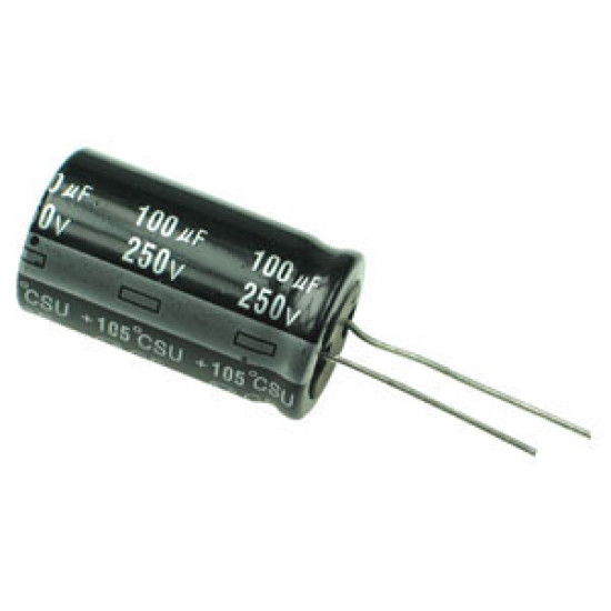
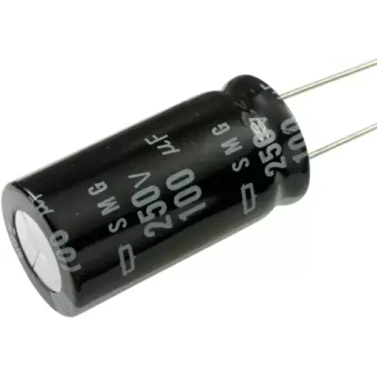
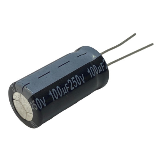
100uF 250V Radial Aluminum Electrolytic Capacitor

100uF 250V Radial Aluminum Electrolytic Capacitor
New
100uF 250V Radial Aluminum Electrolytic Capacitor
KES 200.00
  • Stock: In Stock
  • Model: 100uF 250V Radial Aluminum Ele
  • Weight: 5.20
  • Dimensions: 13.00 x 13.00 x 21.00
  • SKU: 539

Comprehensive Engineering Overview

The 100uF 250V Radial Aluminum Electrolytic Capacitor is an industrial-grade passive component engineered specifically to satisfy the rigorous performance demands of offline power systems, high-voltage energy storage architectures, and audio amplification networks. Characterized by a high capacitance density packed within an optimized radial form factor, this component acts as a fundamental stabilization element in electrical topologies subjected to direct rectified line voltages. Utilizing high-purity etched aluminum foil coupled with a specialized electrolyte formulation, this capacitor delivers uniform dielectric isolation, reduced dissipation factors, and dependable high-temperature endurance.

Aluminum electrolytic capacitors operate through the generation of a microscopic anodic aluminum oxide layer formed on microscopic etched surfaces. This dielectric layer allows this 100 microfarad device to achieve an extraordinary capacitance-to-volume ratio compared to film or ceramic alternatives while operating continuously at high working voltages up to 250 volts direct current. Built with structural integrity and long-term durability in mind, the capacitor is contained within a heavy-gauge hermetically sealed aluminum can that prevents electrolyte vapor loss and protects the chemical core from external environmental pollutants.

Electrochemical Construction and Internal Architecture

Internally, this radial capacitor consists of alternating layers of high-purity etched aluminum anode foil, high-density cellulose separator paper, and a matching cathode foil. The anode foil undergoes an electrochemical etching process that dramatically multiplies its effective surface area by a factor of hundreds. Following etching, a barrier dielectric layer of aluminum oxide is electrochemically formed across the anode. The microscopic thickness of this oxide layer provides the primary dielectric strength required to withstand continuous 250V potentials without breakdown.

The separator paper is saturated with a conductive, non-aqueous electrolyte fluid that acts as the real physical cathode, conforming precisely to the irregular micro-contours of the etched anode foil. The secondary aluminum foil simply serves as a low-resistance electrical collector to channel charge to the negative terminal lead. The wound cylindrical roll is vacuum-impregnated with the electrolyte to eradicate internal air voids, reducing equivalent series resistance and mitigating the danger of internal corona discharge. This assembly is enclosed in an impact-extruded aluminum canister and sealed using a resilient synthetic rubber bung that accommodates internal thermal expansion while completely restricting outgassing under maximum thermal stress.

Electrical Performance and Ripple Current Handling

At an operating ceiling of 250 volts direct current, this component accommodates transient surge voltages up to 300V without triggering dielectric degradation. Engineered with low Equivalent Series Resistance (ESR), it significantly reduces thermal dissipation caused by high-frequency charging and discharging cycles. When alternating ripple currents traverse the capacitor, internal ohmic heating occurs inside the aluminum foil foils, lead wire stitch tabs, and the bulk conductive electrolyte. Because life expectancy in electrolytic capacitors depends strongly on operating temperature, keeping internal ESR low is essential for minimizing core heating.

The capacitor features exceptional ripple current ratings evaluated at both standard line frequencies of 100Hz and 120Hz, as well as high-frequency switching operating points from 10kHz to 100kHz. With elevated temperature tolerance rated up to 105 degrees Celsius, this device delivers extended service life even when positioned adjacent to thermal generators like power MOSFETs, primary bridge rectifiers, and magnetic transformers. In accordance with the Arrhenius rule of chemical kinetics, operating this component below its maximum rated ambient temperature exponentially doubles its operational lifespan for every 10 degrees Celsius drop in operating temperature.

Pinout and Polarity Configuration

Radial aluminum electrolytic capacitors are fundamentally polarized components that require careful mechanical and electrical orientation to avoid catastrophic failure. The terminals consist of two tinned copper-clad steel leads projecting perpendicularly from the bottom rubber sealing bung:

1. Anode Lead (Positive Terminal): Identifiable by its noticeably longer physical wire lead during factory production. The anode must be connected to the higher electrical potential in the circuit. Direct application of reverse polarity degrades the thin dielectric oxide layer, causing thermal runaway and internal pressure buildup.

2. Cathode Lead (Negative Terminal): Characterized by a shorter physical wire lead compared to the anode. Additionally, the outer insulating polyvinyl chloride sleeve of the capacitor features a continuous, vertical colored stripe printed with minus signs aligned with this terminal lead. This stripe provides an immediate visual indicator during through-hole assembly.

3. Safety Vent Relief Mechanism: Located directly on the top surface of the aluminum can, this engineered cross-shaped or circular score line acts as a mechanical pressure relief valve. In the event of extreme overvoltage, reverse polarity, or persistent thermal overstress, the top vent ruptures cleanly to release internal gas pressure safely, preventing uncontrolled fragmentation of the metal case.

In-Depth Application Use Cases

1. Switch-Mode Power Supply (SMPS) Bulk DC Bus Smoothing: In modern offline flyback, forward, and half-bridge power supplies operating from a universal 85V to 265V AC grid, incoming line voltage is rectified into a fluctuating high-voltage DC bus. Positioned directly following the primary bridge rectifier, this 100uF 250V capacitor acts as a reservoir to smooth out 100Hz or 120Hz rectifying ripple, maintaining a steady, low-noise DC rail into primary switching transistors and preventing unwanted duty cycle saturation.

2. Vacuum Tube Audio Amplifier Power Rail Filtering: Vintage and modern audiophile tube amplifiers use plate supply rails (B+ voltage) operating in the 200V to 250V range. This capacitor functions as a dedicated filter node between inductive choke stages and vacuum tube plates. Its generous capacitance attenuates mains hum while its fast instantaneous discharge dynamics preserve deep low-end audio transient response without sagging under heavy output transformer loads.

3. Variable Frequency Drive (VFD) and Motor Inverter Intermediate Stage: Fractional horsepower industrial motor controllers utilize an intermediate DC-link to convert rectified alternating line power into variable frequency PWM drives. This capacitor stabilizes the intermediate direct voltage rail, sinking induced current spikes driven by motor inductance during dynamic regenerative braking and shielding input rectifiers from reflected inductive spikes.

4. Offline Solid-State LED Driver Power Factor Stages: High-wattage architectural and commercial LED luminaires demand stable, flicker-free currents. Installed downstream from active Power Factor Correction (PFC) boost stages, this capacitor filters high-frequency current harmonics generated by high-speed silicon carbide or MOSFET switches, guaranteeing smooth DC feed to current-regulating buck converters and extending total system reliability.

5. Electronic Ballast Circuits for Gas Discharge Lamps: Fluorescent and high-intensity discharge (HID) ballasts convert mains frequency into high-frequency resonant power to sustain arc currents. This capacitor acts as a primary energy reservoir, sustaining the high continuous direct voltage required to supply half-bridge resonant inverters while withstanding harsh ambient operating temperatures inside sealed luminaire housings.

6. Continuous Uninterruptible Power Supply (UPS) Holdup Buffers: Critical battery backup architectures rely on momentary reservoir capacitors to supply energy during sub-cycle transfer times when transitioning between AC line power and battery-inverter systems. The 100uF storage capacity at 250V provides the necessary holdup time for local DC control circuitry, microprocessors, and gate drivers to ensure an uninterrupted transition without system reboot.

7. Piezoelectric Transducer and Ultrasonic Drivers: High-power ultrasonic cleaners, medical atomizers, and industrial welding drivers require a sustained, stabilized high-voltage DC supply to drive primary transformer stages. This component absorbs inductive current reflections from resonant piezoelectric crystals, safeguarding output driver stages against destructive overvoltage ringing.

8. Medical Diagnostics and Analytical Instrumentation Power Supplies: Sensitive diagnostic equipment, such as chromatography detectors, electrophoresis power units, and patient monitoring power modules, demand low baseline ripple and ripple voltages on intermediate stages. The 100uF 250V capacitor attenuates electromagnetic interference and suppresses transient bus spikes, ensuring precision data acquisition and medical grade safety margins.

PCB Layout, Mounting, and Assembly Considerations

To maximize the functional lifespan and performance of this radial capacitor, layout engineers should follow strict PCB design principles. The capacitor must not be placed directly adjacent to high heat sources, such as heat sinks, high-wattage power resistors, or magnetics. Thermal radiation from neighboring components increases internal ambient temperatures and shortens the operating lifetime of the liquid electrolyte.

Trace routing should incorporate wide copper tracks between the capacitor leads and switching nodes to minimize external series inductance. Ground planes surrounding the cathode lead must be kept robust to ensure clean return paths for high-frequency switching ripple currents. When using wave soldering, preheat temperatures and dwell times must be controlled precisely to prevent thermal degradation of the lower rubber bung seal. Following soldering, flux cleaning solvents should be non-chlorinated to avoid halogen ion penetration through the rubber bung, which can initiate electrolytic corrosion on the internal aluminum foil.

Ginō Ginō AI - Nerokas AI Assistant
✕
Jambo! I am Ginō, a Nerokas AI Assistant and Africa's best Open Hardware Facilitator AI agent here to help. In order to serve you better and to help me give you accurate shipping estimates as we begin, could you please tell me your name and your location/city?

You can also ask about any hardware or type I'd like to order, I am looking for..., you can also LIST all SKUs & Quantity of desired items from our website here for me to help you Checkout automatically at anytime to fast-track your requests and orders.