


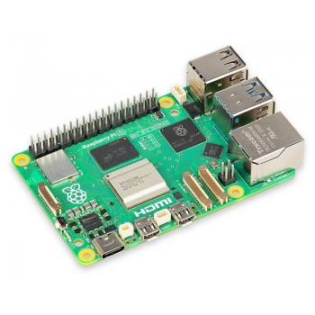


How to Control the Raspberry Pi GPIO using C

A low-level language
like C is more efficient in programming microcontrollers because it is closer
to machine language. In this tutorial, you will learn how to use the
general-purpose input/output pins (GPIO) of Raspberry Pi using C.
Things you need:
- Raspberry Pi
- LED
- Resistors
- Breadboard
- Jumper wires
This tutorial assumes
you already have the basic knowledge in Raspberry Pi. If you need a refresher,
kindly check these previous starter tutorials part 1 and part2.
Table Of Contents
GPIO
GPIO, also known as
General-Purpose Input/Ouput, is a bi-directional digital signal pin commonly
found in microcontrollers and electronic circuit boards. A bi-directional pin
can either output 3.3V when programmed HIGH or 0V when programmed LOW, or act as
an input for sensors. Moreover, they have no dedicated function and are only
used when its user needs to work with auxiliary electronic components outside
of its system.
The Raspberry Pi
includes 2 columns of GPIO pins along the edge of the board. These pins are
very handy for a portable computer like Pi because, with it, you can already
read sensor data, spin motors, drive LCD displays, and etc.
Pinout
The Raspberry Pi uses
a standard male header layout for its GPIO. It was initially 26 pins but was
upgraded to 40 while retaining the original pinout.
Furthermore, there are
two numbering schemes that reference to the pin numbers. One is the Broadcom
chip-specific pin numbers layout (BCM) and another is the P1 physical pin
numbers layout.
The BCM layout is the
standard. In Figure 1 you will see the BCM names on the labels while the
numbers inside the circles are P1.

Figure 1: Raspberry Pi GPIO Pinout
Alternatively, you can view the pinout directly in the terminal using the command, pinout. The pinout command also shows you a labelled graphic of the Pi and some details on its hardware components.

Figure 2: Pinout in Terminal
If you scroll down,
you will see the BCM pinout in colored labels along with the P1 pinout in
parentheses. While the usage of these numbering schemes varies with the API
used, the most common way for BCM is by directly referring to its GPIO number.
For instance, if you want to use GPIO2, simply indicate 2. If you’re using the
P1 scheme, it changes to 3.

Figure 3: Pinout in Terminal 2
Now that we’re familiar with the pinout, let’s now assemble the hardware and move on with our sample project.
Preparing the Hardware
In this tutorial, we
are going to control 4 LEDs using the wiringPi library in the Raspberry Pi. In
order to do that, you will need the following components:
Connect them as shown in Figure 4.

Figure 4: Hardware
The Code
Copy the code to your
favorite code editor or IDE.
#include <wiringPi.h>
const int i, leds[4] =
{2,14,17,23};
void blink (const int
led)
{
digitalWrite(led, HIGH);
delay(30);
digitalWrite(led, LOW);
delay(30);
}
int main(void)
{
wiringPiSetupGpio();
for (int i; i<sizeof(leds); i++)
{
pinMode(leds[i],OUTPUT);
delay(10);
}
while(1)
{
for (int j = 0; j < 4; j++)
{
blink(leds[j]);
}
}
return 0;
}Copy
Code Explanation
You need the wiringPi.h library to work with the Raspberry Pi GPIO.
WiringPi
WiringPi is an
Arduino-based library written in C. It is used as an interface to the Pi’s
GPIO. Moreover, it includes a command-line utility called gpio which
can be used to program the GPIO from shell scripts.
WiringPi is included
in the standard Raspberry Pi OS package so no need to install it. However, if
by chance you’re using an older version of the Pi, you can enter this command
to install it:
git clone git://git.drogon.net/wiringPi
cd wiringPi
git pull origin
./buildCopy
Setup
To use the wiringPi
library, there must be an include line in the beginning of the sketch.
#include<wiringPi.h>Copy
After that, initialize
the GPIO using
wiringPiSetup();Copy
or
wiringPiSetupGpio();Copy
The main difference between the two is that wiringPiSetup() uses the P1 numbering scheme while wiringPiSetupGpio() uses the standard BCM scheme.
Setting the Pin Mode
Assigning the pin mode
of the GPIO to either input or output is easy. Simply enter:
pinMode(pin number,
OUTPUT or INPUT)Copy
Familiar isn’t it?
It’s the exact same function in Arduino! Well, it makes sense since both use
Wiring libraries as part of their core software package. Also, take note that
the pin number depends on the numbering scheme you specified in the setup
section.
Other Functions
As you may have
guessed, in order to send a HIGH or LOW signal to the pins, you also have to
use the same command with the Arduino.
digitalWrite(pin
number, HIGH or LOW)Copy
And to read the data
from a digital sensor:
digitalRead(pin number)Copy
Finally, to add
delays.
delay(time in milliseconds)Copy
Creating the C file
It’s true that the
Arduino syntax remains in the WiringPi library but it doesn’t include the usual
training wheels of the Arduino environment. There are no void setup() and void loop() –
there’s just int main(). Also, you don’t have the luxury of compiling
and running the program in a single button press. You need to build it using
make.
First, open the
terminal and create the file with the Nano editor. The editor or IDE is not
important so choose what you’re comfortable with. In this tutorial however, we
will use Nano.
nano GPIOc.cCopy
This will open a Nano
editor in place of your terminal. If you want to keep the terminal open, enter:
nano GPIOc.c &Copy
Next, copy the sketch above and paste it into Nano. Press save and return back to the terminal.
Running the Program
If you’re coming from
the Python tutorial, you probably have a 1-liner guess in
your mind that looks like this, 'c GPIOc.c‘, that can execute the program
in the terminal.
Unfortunately, that
will not work in C. Python is special because it has a cross-platform Python
interpreter that works in all devices with a single command in the terminal.
For traditional languages like C, a compiler is needed to build the executable
file. To do that, enter:
gcc -o GPIOc GPIOc.c -l
wiringPiCopy
This command will
create a GPIOc.exe file from your GPIOc.c sketch. The additional “-l wiringPi”
lines loads the library so that the compiler understands your code.
A successfully
compiled sketch won’t produce any messages.
Now to run the
program, enter:
sudo ./GPIOcCopy
Note that since it’s
already an executable file, you don’t need any other software to run the
program. To exit the program, press CTRL + C.
That’s it! Check this link here, if you want to do the same thing but with the Python programming language.

Comment